- Index
- Catalog
- THREAD GRINDING MACHINES WITH CNC
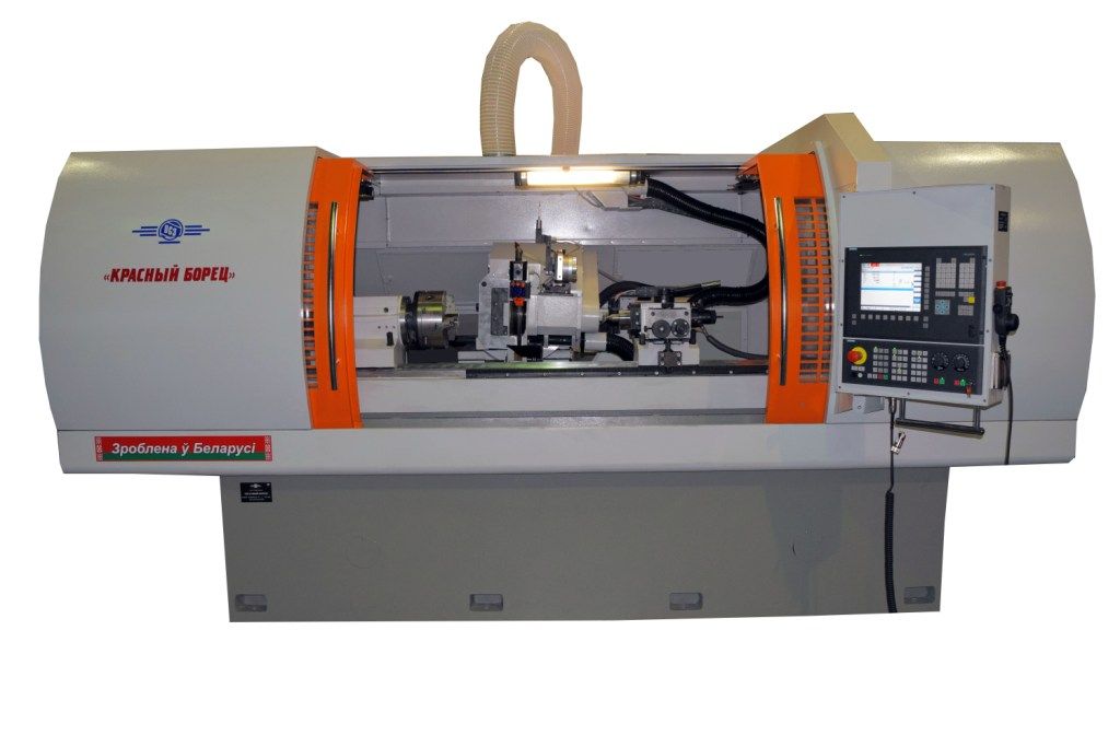
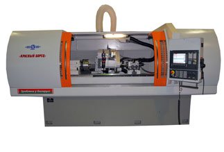
- THREAD GRINDING SEMIAUTOMATIC MACHINE WITH CNC OSH-633F3 VERSION 04
THREAD GRINDING SEMIAUTOMATIC MACHINE WITH CNC OSH-633F3 VERSION 04
DESCRIPTION
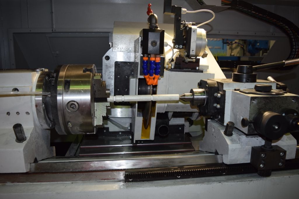
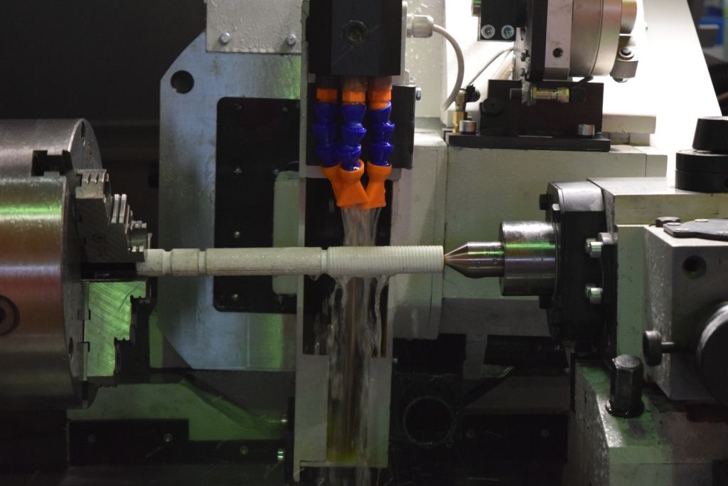
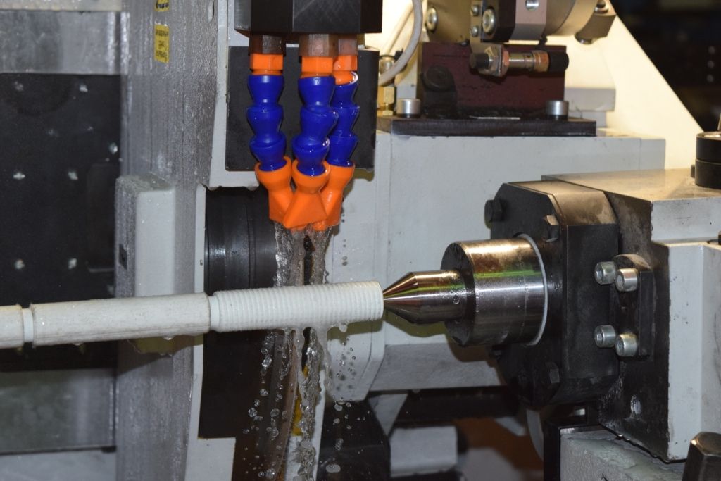
Semiautomatic machine is designed for external grinding of outward, cylindrical and conic left and right, single - and multistart threads of different profile.
Semiautomatic machine has an arrangement with traveling in longitudinal and cross directions wheel head relative to motionless rotating part.
Wheel head has possibility of turning to the left and to the right relative to the axis of machined part in vertical plane on the helical groove angle of ascent.
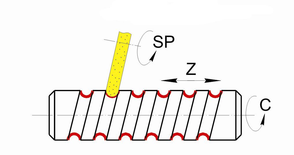
Kinematic diagram of machine must provide the following motions:
- cross travel of wheel head – coordinate X;
- longitudinal travel of sleds with wheel head -
coordinate Z;
- angular turn of wheel head in vertical plane
(the helical groove angle of ascent) – coordinate A;
- machined part rotation – coordinate C;
- grinding wheel rotation - axis Sp;
- rotation of dressing diamond roller;
- diamond roller longitudinal travel – coordinate W;
- diamond roller vertical travel – coordinate V;
- wheel fixation over coordinate А;
- touch sensitive tool input and output into position of hunting the middle of profile of thread groove.
DESIGN ADVANTAGES
- CNC system Sinumerik 840Dsl with servo drives Sinamics 120.
- Linear and circular feedback sensors of the firm «Fagor» over programmable coordinates – wheel head cross travel is coordinate X, - sleds with wheel head longitudinal travel is coordinate Z, - wheel head angular turn in vertical plane (turn of thread inclination angle) is coordinate A, - machined part rotation is coordinate C.
- Electric cabinet of own production with refrigerating plant of the firm «Rittal».
- High precision gapless ball-screw transmissions for longitudinal travel of sleds, cross travel of wheel head.
- Touch sensitive tool of the firm «Renishаw».
- Enclosure of working zone of “cabinet type”.
- Frequency adjustment of wheel head spindle revolutions.
- Contactless transducers and limit switches of the firm «Balluff».
- Closed roller linear guide ways.
- High precision angular ball bearings for work head spindle and wheel head rotary axis.
- Contour dressing by diamond roller from headstock mechanism.
- Technical specifications
- Design description
- Delivery set
- Options
- Video
- Reference-list
- Reviews
-
Length of machined workpiece
1450 mm
-
Diameter of machined workpiece
250 mm
-
Main drive power
7,5 kw
-
Grinding spindle rotation frequency
2100...4500 rpm
-
Ground thread diameter
3...200 mm
-
Maximum angle of ascent of ground thread helical curve
+-30 degrees
-
Overall dimensions (length x width x height)
4300 x 3560 x 2600 mm
-
Mass
8000 kg
Machine has an arrangement with traveling in longitudinal and cross directions wheel head relative to motionless rotating part.
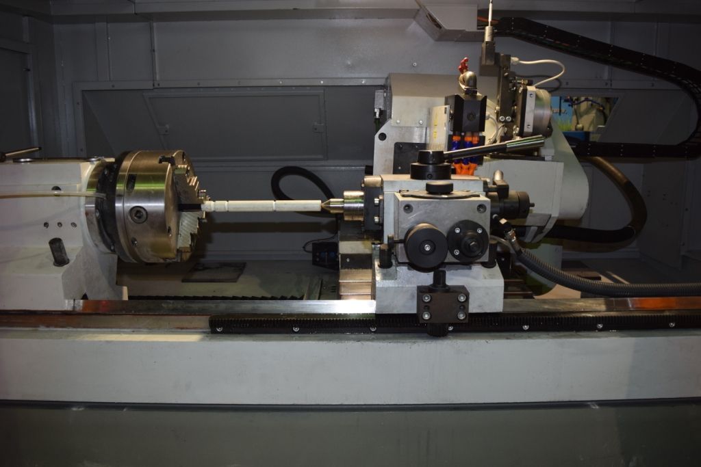
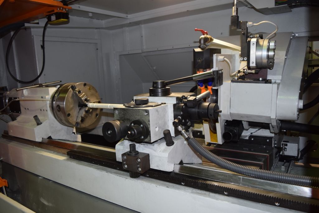
Headstock, tailstock, rest and work piece supports are fastened rigidly on upper front base surface of cast-iron bed.
Wheel head has possibility of turning to the left and to the right relative to the axis of machined part in vertical plane for thread grinding. Rotary wheel head (coordinate “A”) turns on wheel head on the necessary helical groove angle of ascent. Turn on 0 degree is necessary always when grinding wheel dressing.
After finishing of turn the movable units are fastened and only after fastening it is possible to start the cycles of grinding and dressing.
Orientation as per turn of thread is provided by touch sensitive tool.
Sleds travel (coordinate “Z”) is realized by longitudinal feed mechanism fastened on the right pad of the bed. Feed mechanism screw rotation is realized by synchronous motor.
Control of sleds travel value is realized by optical ruler.
Wheel head travel (coordinate “X”) is realized by mechanism of cross travels fastened on the rear face of sleds.
Rotation of mechanism screw is realized by synchronous motor. Rotation of grinding wheel (coordinate “Sp”) is realized from electric motor with frequency adjustment for supporting the constant speed of cutting for wheel wear.
Rotation of machined part (coordinate “C”) is realized by warpage mechanism fastened on work head spindle flange. The part is based in centres of headstock and tailstock. Rotation of work head spindle is realized from servo motor through reduction gear.
Two-axis mechanism of dressing by rotating diamond roller is installed on wheel head.
Coolant –lubricant of trade mark МР10 or similar with it is used when grinding, productivity of coolant-lubricant feed pump is Q = 80 l/min.
Control of machine operation is realized through program. All modes of grinding (feeds, travel speeds, tool and part rotation frequency) are determined by parameters. Machining modes can be changed also without changing the control program.
Grinding method: grinding the thread profile by one profile grinding wheel. Grinding wheel profile dressing is realized automatically according to program by rotating diamond roller.
- machine assemble with heads and touch sensitive tool;
- grinding wheel dressing mechanism;
- hydraulic station;
- coolant feed and treatment system;
- coolant-lubricant heat setting refrigerating plant;
- aerosol exhaust plant;
- electric cabinet;
- control desk with CNC system;
- set of spare parts and attachments for guarantee operation term;
- set of in-line technical documentation in English.
Device of machined parts blow-off. This option includes a special gun with polyvinyl pipe through which air from outward network is supplied under pressure. Air feed is realized onto block installed on machine bed and further on to the gun which is located on the front surface of bed in the zone of operator’s location. The operator can produce machined parts blow-off by compressed air from table or electromagnetic chuck by pressing the gun lever.
Unit for coolant-lubricant feed and its treatment.
Plant for aerosol exhaust from the machining zone.


