- Index
- Catalog
- CIRCULAR GRINDING MACHINES, FACE CIRCULAR GRINDING MACHINES
- SEMI-AUTOMATIC CIRCULAR GRINDING MACHINE WITH CNC OSH-660F3 VERSION 28
SEMI-AUTOMATIC CIRCULAR GRINDING MACHINE WITH CNC OSH-660F3 VERSION 28
DESCRIPTION
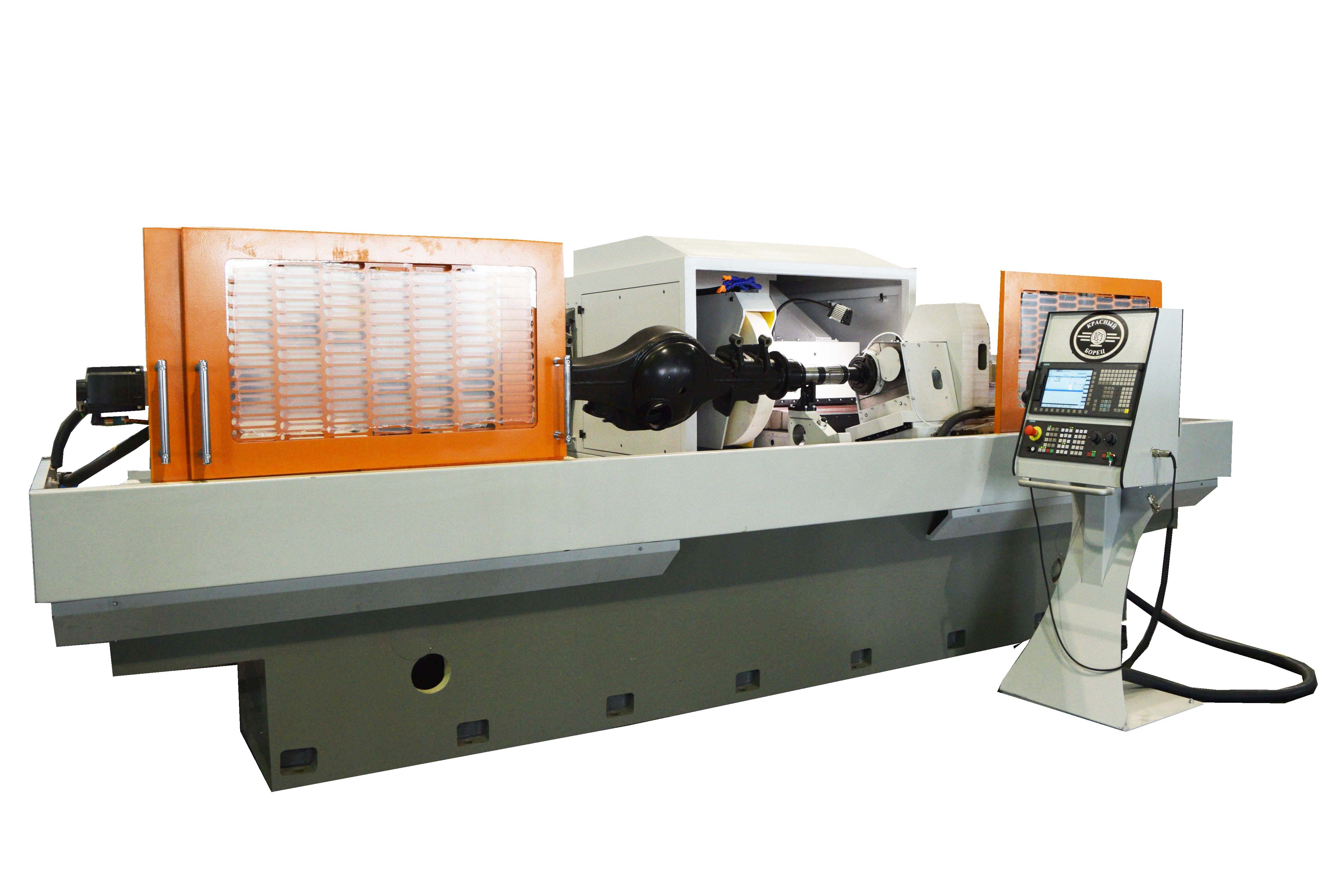
Semi-automatic circular grinding machine with CNC mod. OSH-660F3 version 28 is designed for outward grinding of smooth cylindrical and conical surfaces type of rotation body.
The scope of application of the machine is individual and serial production enterprises.
The kinematic scheme of the machine provides the following movements:
- rotation of the workpiece (coordinate Sp1);
- rotation of the grinding wheel (Sp2 coordinate);
- cross movement of the wheel head (X coordinate); - table longitudinal travel (Z coordinate);
- the top table turn to the specified angle manually.
DESIGN ADVANTAGES
- CNC system Sinumerik 828D of the firm, “Siemens” with servo drives Sinamics;
- Linear feedback sensor over the X-coordinate;
- Electric cabinet equipped with refrigerating unit;
- Closed roller linear guides over the X coordinate;
- High-precision gapless ball-and-screw drives in feed drive mechanisms;
- High-precision angular contact ball bearings for wheel head spindle, headstock spindle ;
- Device for dynamic balancing of the grinding wheel for external grinding with the function of GAP;
- Inprocess gage for external grinding;
- The open type guard of the working area.
- Technical specifications
- Design description
- Delivery set
- Options
- Video
- Reference-list
- Reviews
-
Machine accuracy class
P
-
Length of the workpiece to be installed
2800 mm
-
Outer diameter of the workpiece to be installed
50...560mm
-
Main drive power
18,5 kW
-
Overall dimensions of the machine with auxiliary equipment (length x width x height)
5500x4200x2480 mm
-
Outer diameter of the surfaces to be processed
50...560 mm
-
Length of the surfaces to be processed
2700 mm
-
The frequency of rotation of the workpiece
20...280 rpm
-
Installed grinding wheel outer diameter for external grinding
750 mm
-
Installed grinding wheel internal diameter for external grinding
305 mm
-
Installed grinding wheel height for external grinding
100 mm
-
Main drive spindle rotation frequency
1100...2800 rpm
-
The speed of longitudinal setup travels
6 m/min
-
Speed of transverse setup travels
6 m/min
-
Discreteness of movement on controlled coordinates
1 mkm
-
The table maximum travels (Z coordinate)
2900 mm
-
The wheel head maximum travels (X coordinate)
400 mm
-
Weight of the machine with additional equipment
22000 kg
The layout of the machine.
The machine has a layout with a movable table moving along the axis of the part (Z coordinate) on which the work piece is installed, and a wheel head moving in the transverse direction (X coordinate). The work head with an electric drive and the tailstock are attached to the working surface of the upper table, which can be rotated at an angle of +3º...-3º.
The top table is mounted on a movable table. Left rear of the bed the cooling system is installed, to the right, there is a hydraulic station, and right rear there is the electric cabinet.
The work head with an electric drive and the tailstock are attached to the upper working surface of the movable table. The cross movement of the wheel head is carried out along the linear rolling guides by means of a ball-screw transmission. The wheel head makes a transverse movement and consists of a body and a spindle assembly for external grinding.
Surface treatment and the grinding wheel dressing is performed automatically according to the control program, installation and removal of the part are carried out manually or by means of lifting and unloading devices. The machine automatically compensates for the amount of removal of the grinding wheel profile during dressing.
The grinding wheel dressing mechanism is installed on the machine table. Dressing the periphery of the main drive grinding wheel is carried out using a dressing diamond, by moving the wheel head and the table along two coordinates.
The base of the processed part is made in the centers of the headstock and tailstock.It is possible to use lunettes. Water-based coolant is used for grinding.
The control system provides:
- manual movement on the coordinate axes, manual grinding;
- processing of the part using the control program;
- the grinding wheel dressing according to the programmed cycle with compensation for wear of the grinding wheel;
- machine assembled;
- coolant supply and cleaning system; - hydraulic station;
- electric automation cabinet, control panel with CNC system;
- lunette for installing parts ø40 ... 120 - 2 pieces;
- rest for installation details ø 100...350 – 1pc;
- grinding wheel flanges-2 sets (1set is on the machine);
- device for static balancing of the grinding wheel assembled with flanges;
- set of spare parts, tools and accessories (including abrasive and diamond tools, mandrel for balancing the grinding wheel, center);
- set of operational and technical documentation
Equipment of the wheel head with a device for dynamic balancing of the grinding wheel. This option includes a flange-type balancing head with a non-contact transmitter, vibration sensor and electronic device. The use of this device allows automatic balancing of the rotating grinding wheel on the machine with minimal imbalance.
Equipped with an exhaust device. When the machine is equipped with a cabinet fence of the working area, it is possible to use a device for sucking aerosol formed during the grinding process. This device is a welded base on which a welded cylinder with a funnel, an engine with an impeller, a filter element, covers with pipes and a sleeve are attached. The exhaust device can operate independently in both manual and automatic mode and allows the removal of aerosol vapors from the treatment area +0.0025 mm.
Equipped with an inprocess gage. The device for active monitoring of cylindrical diameters of processed parts includes a bracket with two measuring heads with orientation function and measuring contacts, as well as an electronic device with a control panel. The electronic device is attached to the machine control panel. The use of an inprocess gage allows you to ensure stable obtaining of the size of the processed diameter within the limits.


