- Index
- Catalog
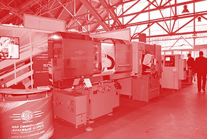
- CIRCULAR GRINDING MACHINES, FACE CIRCULAR GRINDING MACHINES
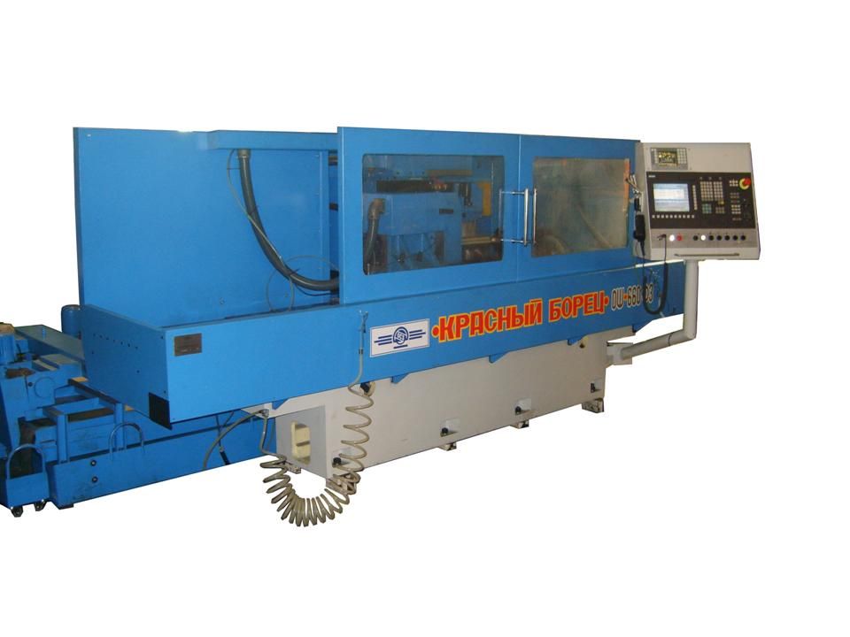
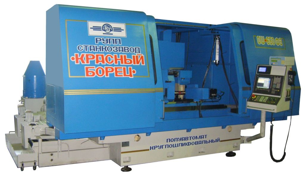
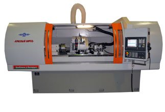
- SEMI-AUTOMATIC FACE-CIRCULAR GRINDING MACHINE WITH CNC OSH-650F3
SEMI-AUTOMATIC FACE-CIRCULAR GRINDING MACHINE WITH CNC OSH-650F3
DESCRIPTION
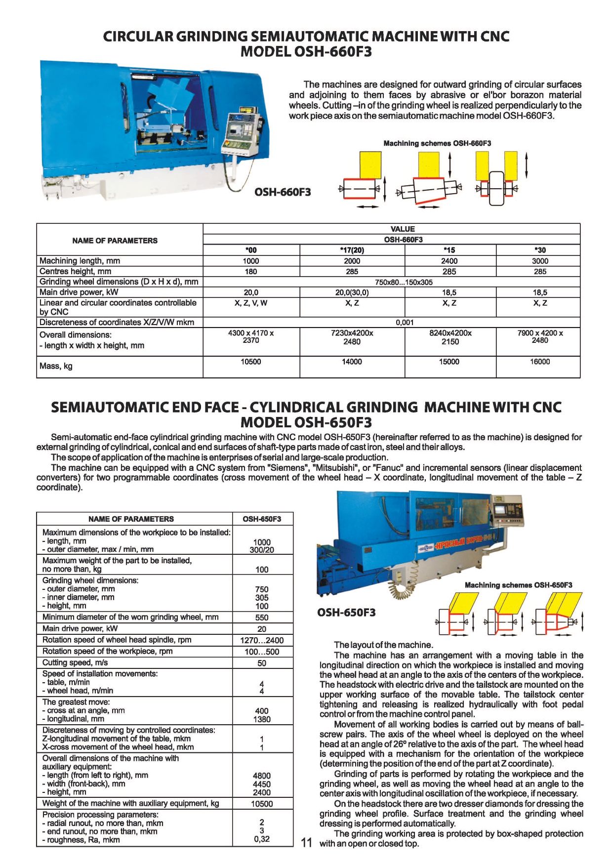
Semi-automatic face-grinding machine with CNC model OSH-650F3 is designed for outward grinding of cylindrical, conical and face surfaces of parts type of shaft from cast iron, steel and their alloys.
The scope of application of the machine is enterprises of serial and large-scale production.
The machine can be equipped with a CNC system and incremental sensors (linear displacement converters) for two programmable coordinates (transverse movement of the wheel head – X coordinate, longitudinal movement of the table – Z coordinate).
The kinematic scheme of the machine must provide the following movements:
- movement of the wheel head (X coordinate);
- longitudinal movement of the table (Z coordinate); - rotation of the grinding wheel (axis Sp1);
- rotation of the workpiece (SP2 axis);
- Technical specifications
- Design description
- Delivery set
- Options
- Video
- Reference-list
- Reviews
-
Length, min/max of the workpiece to be installed
1000 mm
-
Outer diameter, min/max of the workpiece to be installed
300/200 mm
-
Grinding wheel diameter
750 mm
-
Grinding wheel height
10 mm
-
Grinding wheel bore diameter
305 mm
-
Main drive power
20 kW
-
Cutting speed
50 m/s
-
Maximum mass of installed work piece (together with mass of fixing elements)
100 kg
-
Length of the machine with auxiliary equipment
4800 mm
-
Width of the machine with auxiliary equipment
4450 mm
-
Height of the machine with auxiliary equipment
2400 mm
-
Weight of the machine with auxiliary equipment
10500 mm
-
Discreteness by controlled coordinates X/ Z
1
-
Minimum diameter of the worn grinding wheel
550 mm
-
Rotation speed of the wheel head spindle
1270...2400 rpm
-
Rotation speed of the workpiece
100...500 rpm
-
Speed of the table adjustment travels
4m/min
-
Speed of the wheel head setting movements
4m/min
-
Maximum cross travel at an angle
400 mm
-
Maximum longitudinal travel
1380 mm
-
Tolerance of radial runout of treated surfaces
2 mkm
-
End run-out tolerance of treated surfaces
3 mkm
-
Roughness of the treated surfaces
0,32 mkm
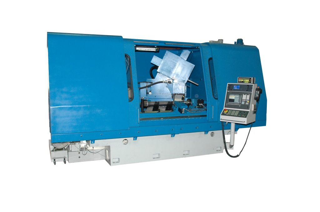
The machine has a layout with a moving table in the longitudinal direction on which the workpiece is installed and the movement of the wheel head at an angle to the axis of the centers of the workpiece. The headstock with electric drive and the tailstock are mounted on the upper working surface of the movable table. The tailstock center tightening and wringing is realized hydraulically with control from the foot pedal or from the machine's control panel.
Movement of all working bodies is carried out by means of ball-screw pairs. The axis of the grinding wheel is rotated on the wheel head at an angle of 26.34 degrees relative to the axis of the part. The wheel head is equipped with a mechanism for the orientation of the workpiece (determining the position of the part end by the Z coordinate). Hydraulic equipment is made by a separate unit and is installed to the right of the machine, and the cooling system at the back to the left. On the right side of the back there is an electric cabinet with electrical equipment, and in front there is a control panel with a CNC system.
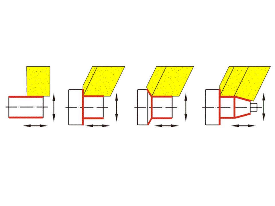
Grinding of parts is performed by rotating the workpiece and the grinding wheel, and also by movement of the wheel head at an angle to the center axis with longitudinal oscillation of the workpiece, if necessary.
On the headstock of the front two dresser diamonds for the grinding wheel profile dressing are mounted. Surface treatment and dressing of the grinding wheel is performed automatically according to the control program, installation and removal of parts are carried out using the customer’s special hoist cable device.
The machine automatically compensates for the amount of the grinding wheel profile removal when dressing, dressing the faces of the grinding wheel is performed by linear interpolation of movement along the control coordinates (Z – moving the table and X - moving the wheel head).
The working area of grinding is protected by a box-shaped protection with an open or closed top.When grinding, water-based coolant is used.
- machine assembled (with wheel head, headstock and tailstock);
- coolant supply and cleaning system;
- hydraulic station;
- electric automation cabinet;
- control panel with CNC system;
- a set of spare parts and accessories, quick-wear parts for the warranty period (12 months) of operation;
- grinding wheel flanges assembly – 2 sets (1 set is installed on the machine);
- mandrel for static balancing of the abrasive wheel assemblied with faceplate;
- device for the grinding wheel static balancing;
- abrasive wheels 2 pcs. (750 x 305 x 100) mm;
- set of operational and technical documentation in 1copy;
- universal processing program.
Coolant supply and cleaning system with magnetic separator and filter conveyor. This option includes a tank with a pump for supplying coolant to the treatment area and a filter conveyor with a roll filter cloth, as well as a magnetic separator, which is mounted on the frame of the filter conveyor. Coolant filtration occurs first through a magnetic separator, then through a filter conveyor. The throughput of the magnetic separator is 100 l / min, and the filter-conveyor is 200 l / min.
Cabinet fencing of the working area of processing. The machine guard is a welded frame mounted on the bed and is designed to protect against splashing of coolant during operation. The cabinet type fence is a frame with a closed top and a movable sliding door.
Equipment of the wheel head with a device for dynamic balancing of the grinding wheel. This option includes a flange-type balancing head with a non-contact transmitter, vibration sensor and electronic device. Using this device allows automatic balancing of the rotating grinding wheel on the machine with minimal imbalance.
Equipped with a device for monitoring the position of the part. This option includes a mechanism consisting of a bracket on which an axis with a lever is fixed. A touch sensor with a probe is attached to the lever. The lever is rotated on the axis using a linear pneumatic cylinder. Using the Renishaw touch sensor, the workpiece is touched and its linear coordinates are determined, which are then used in the processing control program.
Equipped with an inprocess gage. The inprocess gage of cylindrical diameters of processed parts includes a bracket with two measuring heads with orientation function and measuring contacts, as well as an electronic device with a control panel. The electronic device is attached to the machine control panel. The use of the active control device allows you to ensure stable obtaining of the size of the processed diameter within ± 0.0025 mm