- Index
- Catalog
- SURFACE GRINDING MACHINES
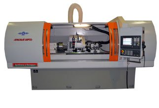
- HORIZONTAL SPINDLE COMPOUND TABLE SURFACE GRINDING MACHINE OSH-400 (ORSHA -40110)
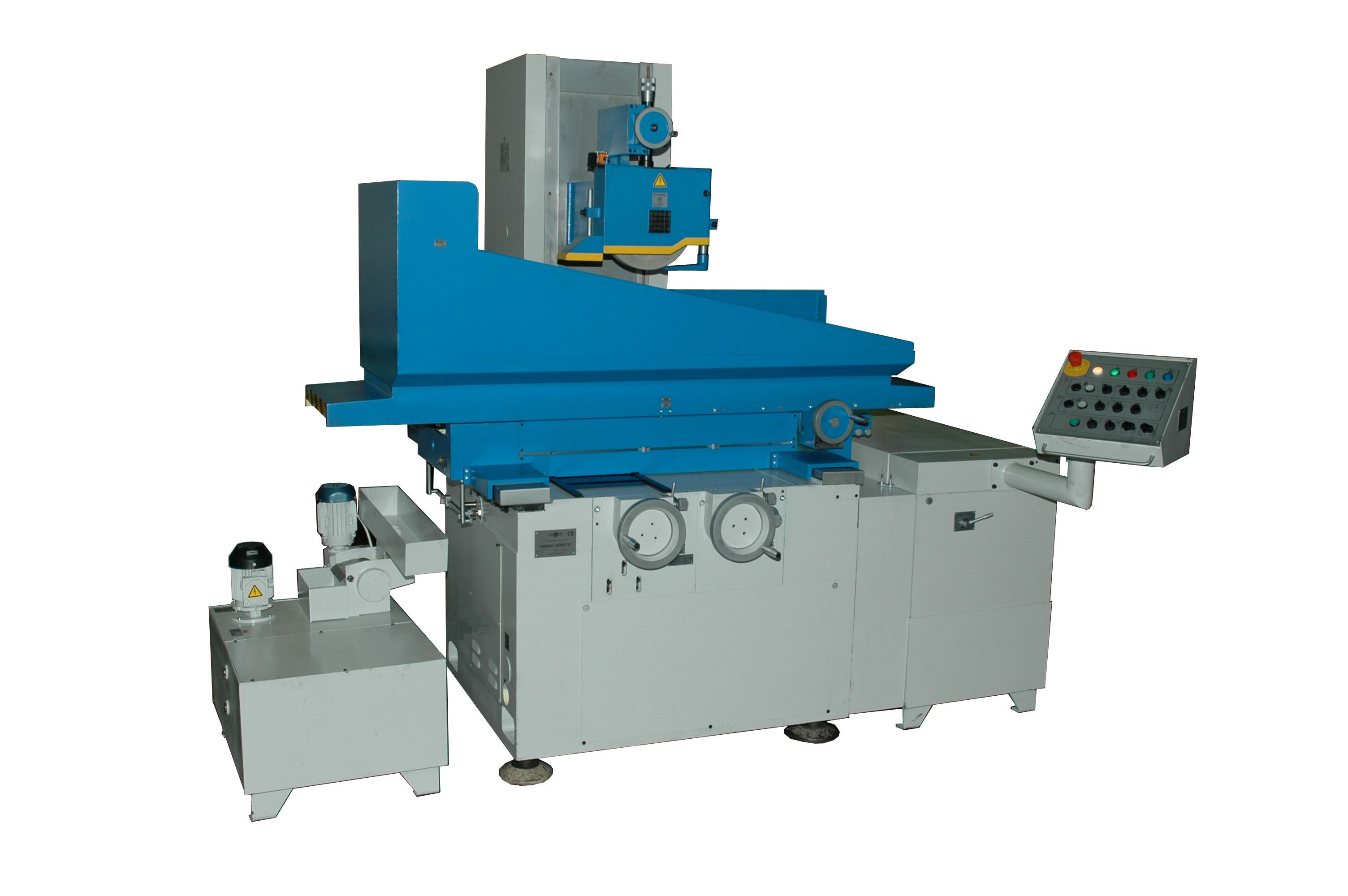
HORIZONTAL SPINDLE COMPOUND TABLE SURFACE GRINDING MACHINE OSH-400 (ORSHA -40110)
DESCRIPTION
Surface grinding machines are designed for high precision processing of flat surfaces of different items from ferrous and non-ferrous metals and also grinding by wheel face with vertical feed of wheel within limits permissible by grinding wheel housing under conditions of mass, serial and single-piece production.
Kinematic diagram of machine provides the following motions:
- longitudinal automatic travel of table from hydraulic cylinder and manual travel from hand wheel;
- cross automatic travel of compound slide, rapid travel and manual fine and rough travel by hand wheels;
- vertical automatic travel of wheel head, rapid travel, manual fine and rough travel by hand wheels;
- grinding wheel rotation
DESIGN ADVANTAGES
- Components of leading world producers
- Compound slide and wheel head travel is realized on rolling-contact bearings by ball-screw pairs.
- Table travel (coordinate X) is from sliding hydraulic cylinder.
- The use of ground rolling ball-screw pairs in the feed units ensures smooth, high precision, backlash-free positioning.
- Automatic lubrication of bed and table guide ways.
- All working travels on machines are automated.
- The rational design of the bed, compound slide, column, table and wheel head made of iron castings ensures the machine high rigidity and vibration-free operation providing stable precision and purity of machining.
- Technical specifications
- Design description
- Delivery set
- Options
- Video
- Reference-list
- Reviews
-
Machine accuracy class
High
-
Table mirror width
400 mm
-
Table mirror length
1100 mm
-
Dimension of item sample
400 x 150 x 120 mm
-
Flatness
4 mkm
-
Parallelism
5 mkm
-
Roughness of surface machined by wheel periphery, Ra
0,16 Ra
-
Table working feeds
1...25 m/min
-
Wheel head working feeds
0,002...0,08 mm/stroke
-
Compound slide working feeds
0,3...40 mm/stroke
-
Compound slide maximum travels
445 mm
-
Table maximum travels
1160 mm
-
Maximum mass of installed work piece (together with attachment and electromagnetic chuck)
400 kg
-
Maximum distance between table mirror and spindle axis
650 kg
-
Grinding wheel diameter
400 mm
-
Grinding wheel height
40...80 mm
-
Grinding wheel bore diameter
127 mm
-
Main drive power
7,5 kW
-
Grinding spindle rotation frequency
1910 rpm
-
Maximum length of machined surface
800 mm
-
Maximum width of machined surface (without grinding wheel run-out)
400 mm
-
Maximum height of machined surface (when grinding wheel is new)
400 mm
-
Rapid cross travel speed
1400 mm/min
-
Rapid vertical travel speed
300 mm/min
-
Value of cross feed limb division
0,05 mm/division
-
Value of fine cross feed limb division
0,005 mm/division
-
Value of vertical feed limb division
0,002 mm/division
-
Value of fine vertical feed limb division
0,0005 mm/division
-
Hydraulics drive power
2,2 kw
-
Vertical travels drive power
0,37 kw
-
Cross travels drive power
0,12 kw
-
Mains voltage
380 V
-
Mains frequency
50 Hz
-
Cooling tank volume
100 L
-
Hydraulic drive station tank volume
125 L
-
Overall dimensions (length x width x height)
3800 x 2540 x 2140 mm
-
Mass
4150 kg
The machine base is the bed on which compound slide, column, control panel, cross and vertical feeds mechanism are installed.
Machine compound slide provides longitudinal and cross table travel.
Column ensures vertical travel of wheel head.
All working travels on machine are automated.
Longitudinal table travel is realized by hydraulic cylinder.
Automatic and rapid travel of compound slide is realized through the belt transmission from induction electric motor.
Automatic vertical feed is realized from hydraulic motor through reducer and rapid travel is from induction electric motor through the belt transmission and reducer.
Manual travel of compound slide, wheel head and table is executed by hand wheels.
Spindle rotation is realized by induction electric motor.
Machine hydraulic station is fulfilled as a separate unit and installed to the right from the machine.
Machine control panel is located on the bracket which is fastened to the bed. Cooling system unit is installed from the left side of machine.
COLUMN
Column is mounted on the rear wall of the bed and serves for realization of vertical travels of wheel head which is installed and rigidly fastened on its top surface.
Guide ways of surface are formed by column itself and the bars screwed onto the bed. Preload in system of vertical guide ways is achieved :
- in the plane parallel to the grinding spindle axis - by means of rigid bushings and force of disk springs;
- in the plane perpendicular to the grinding spindle axis – at the expense of guide ways of V-shaped form use.
Vertical travels worm-and-wheel gearbox is fastened to the lower plane of the column.
LEFT CROSS GUIDE WAY
Left linear slide roller bearing has U-shaped form in section, perceives vertical and side loads. For ensuring high rigidity and accuracy of cross travel of compound slide U-shaped guide way is assembled with preload which is created with wedge by means of the screw, then the wedge is fixed by the screws.
COMPOUND SLIDE
Compound slide ensures cross and longitudinal travel of table. Longitudinal linear bearings (V-shaped and flat ones) over which the table travels, is located on top plane of compound slide. Hydraulic cylinder of table drive is rigidly fastened between longitudinal guide ways.
Bracket which is connected with the nut of ball-screw pair of cross feed mechanism is fastened to the lower surface of compound slide. The sliding bar over which table reverse cams travel is installed on the front wall of compound slide, under guard board. Tabs interacting with contactless switches located on table are installed on cams. Position of cams is adjusted depending on the length of machined part. Mechanism of table manual travel is fastened from the front, to the left on compound slide.
TABLE
Table has working surface with three Т-shaped slots for installation and fixation of machined parts, electromagnetic chuck or setting fixture. On lower plane of table the longitudinal slideway bearings - V-shaped and flat ones are located and also toothed rack which provides the manual travel of table from the gear of manual travels mechanism . Brackets are stiffened over edges of lower table surface. Rods of hydraulic cylinder are connected to those brackets. Protection of working zone is installed on top plane of the table.
Collection of coolant takes place in the table bath, and discharge – through aperture in the rear wall of table into collector and further on to cooling tank.
CROSS FEED MECHANISM
Cross feed mechanism provides:
- manual travel of compound slide;
- automatic feed;
- rapid travels;
- hand wheel switching off by electromagnetic clutch during automatic travels of compound slide.
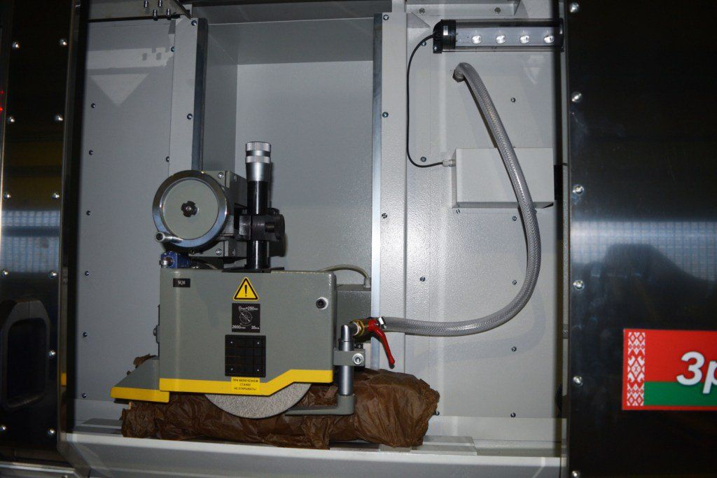
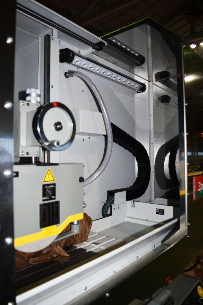
WHEEL HEAD
Wheel head consists of body and spindle. Spindle is installed on high precision radial-thrust bearings assembled with preload.
Supporting thread end of rolling ball-screw pair of vertical travels is fastened rigidly to the lower surface of wheel head body.
Special canals and labyrinths are made in flange with the purpose of providing the protection of leading foot bearings.
VERTICAL FEED MECHANISM
Vertical feed mechanism provides:
- automatic vertical feed;
- manual rough and fine travel of wheel head;
- hand wheel switching off by electromagnetic clutch during automatic travels of wheel head.
COOLING
Cooling consists of welded tank on which electric pump for coolant and magnetic separator for coolant treatment from metal slime are installed. Slime is collected in a separate tank.
Emulsion discharge from the table takes place through collector fastened on compound slide into the tray installed into magnetic separator.
HYDRAULIC CYLINDER
Hydraulic cylinder is installed on top surface of compound slide and realizes reciprocal motion of table. Hydraulic cylinder rods are fastened by nuts to table brackets. Rods are sealed by rubber glands. Table braking by means of special cones is foreseen in the extreme positions of piston stroke.
HYDRAULIC DRIVE STATION
Hydraulic drive station is designed for providing reciprocal travel of table with adjustable speed, output of table into loading zone, vertical feed mechanism drive and realization of centralized automatic lubrication of guide ways.
Station works on clean mineral oils with kinematic viscosity from 30 to 35 mm2/с (r/St) at temperature 40°C designed for hydraulic systems with antioxidant and wear-preventive additives.
Recommended trademarks of oils: ИГЛ-18 ТУ 38.101413-78, ИГП-30 ТУ 38.10141З-78.
LUBRICATION SYSTEM
Lubrication system is designed for centralized lubrication of all guide ways from hydraulic system. It is switched on automatically when machine hydraulic drive is switched on.
Oil enters the lubrication system from hydraulic drive station through filter with filtration accuracy of 25 mkm. Drainage of lubrication is discharged into a sediment box designed for oil cleaning before discharge into hydraulic station. Sediment box is equipped with a magnetic separator.- machine assembled;
- cooling system with pump and magnetic separator of coolant treatment;
- hydraulic station of table drive and lubrication;
- electric cabinet;
- control panel;
- set of quick wearing parts and tools for the period of operation- 3D711AF10-1.OP01.00.0.000.0.00 digital read-out device. This option includes two-coordinate (two-axis) digital read-out device ЛИР-520 over coordinate Z (cross travel of compound slide) and coordinate Y (vertical travel of wheel head). Converter of linear travel over coordinate Z ЛИР-520-1-420-00-05 is installed on compound slide and bed, over coordinate Y ЛИР-520-1-270-00-05 - on column and wheel head, block of digital read-out device is installed on top of plate of the machine control panel.
– master controller; SIMATIC S7-1200 is a new range of microcontrollers for solution of the most different tasks of automation of low level. These controllers have module structure and universal purpose. They are capable to work in real time scale supporting intensive communication data exchange through network of Industrial Ethernet/PROFINET and also PtP. Each CPU S7-1200 is equipped with built-in interface Ethernet which is used for programming and diagnostics, data exchange with other systems of automation, devices and systems of man-machine interface.
- grinding wheel dressing mechanism: - grinding wheel manual dressing mechanism 3D70.P43.00.0.000.0.00-02; - grinding wheel dressing mechanism with electric drive 3D70.P46.00.0.000.0.00-02 Grinding wheel dressing mechanism is installed on top the body of wheel head and designed for dressing the periphery of grinding wheel by dresser diamond. Dresser diamond is installed into poppet sleeve which travels manually by a hand wheel in cross direction. Vertical feed of diamond is produced manually by threaded feed unit.
- 3D711AF10-1.OP03.00.0.000.0.00 device of the machined parts blow-off. This option includes a special gun with polyvinyl pipe through which air is supplied under pressure from extranet. Feed of air is realized onto block installed on machine bed and further onto the gun which is located on the front surface of the bed in the zone of operator location. Operator can produce blow – off of taken from the table or electromagnetic chuck machined parts with compressed air by means of pressing the gun lever.
- drafting device “UV-1200.00.0.000.0.00” The device is designed for extracting the coolant-lubricant mist with impurities of hard dust and fine metal chips.
- 3D711AF10-1.OP05.00.0.000.0.00 industrial vacuum-cleaner. This option includes autonomous vacuum cleaner model 370.P16.00.0.000.0.00 which is connected with grinding wheel housing by flexible plastic hose. Metal hose from vacuum cleaner is connected to the corresponding connector of the machine electric cabinet. Productivity of vacuum cleaner is 800 m3/h, power of electric motor is 1,5 kW, number of revolutions is 2 800 min-1.
- 3D711VF11.OP06.00.0.000.0.00 system of coolant feed and treatment with magnetic separator and filter –conveyor. This option includes tank with pump for coolant-lubricant feed into the zone of machining and filter –conveyor with roller filtering cloth and also magnetic separator which is installed on the frame of filter-conveyor. Filtration of coolant-lubricant takes place at first through magnetic separator , then through filter-conveyor. Capacity of magnetic separator is 50 l/min, of filter-conveyor is 100 l/min.
- electromagnetic and magnetic chuck.
- vertical spindle. Limits of spindle rotation frequencies 6000…24 000 min-1, 5000…30 000 min-1, power 22,0 kW.
- grinding wheels balancing attachment 3E70.P01 3E70.P01 – Maximum diameter of balanced wheel is 320 mm. 3E70.P01-04 – Maximum diameter of balanced wheel is 4000 mm.
- swivel sine square 3E70.P54 Maximum angle of rotation of sine ruler is +600. Maximum angle of rotation of square is +600. Overall dimensions (length x width x height) are 195 x 200 x 200 mm. Mass is 9,5 kg
- 3D711AF10-1.OP04.00.0.000.0.00 centrifuge. When processing nonmagnetic materials the machine can be equipped with one rotor centrifuge which is connected by discharge hose with the tank of coolant-lubricant feed system. Centrifuge consists of hermetic tank inside of which round shell is executed for rotor location. On top the tank is closed hermetically by hinged cover which is clamped by two screw stops. Conic casing head is executed inside the cover for supply of cleaned coolant-lubricant into rotor, outside there is a square with nipple for connection of hose of diversion of cleaned coolant-lubricant from working zone. Control of cover closing is realized by end switch. Rotor of centrifuge is solid aluminium in the form of a cup, rubber cover for slime collection is installed inside the rotor. On top the rotor is closed by aluminium cover with cast impeller. Rotor is based on spindle cone installed in a barrel. Spindle unit with rotor and drive electric motor is hung on studs sealed in crosstrees –blocks to three supports on cylindrical shell of the centrifuge tank. Operation of centrifuge is based on the principle when coolant-lubricant enters the rotating rotor in which under influence of centrifugal field of force fractions precipitation takes place, density of which exceeds the density of cleaned liquid. Level of centrifuge cleaning is 15-20 mkm, power is 1,1-1,5 kW
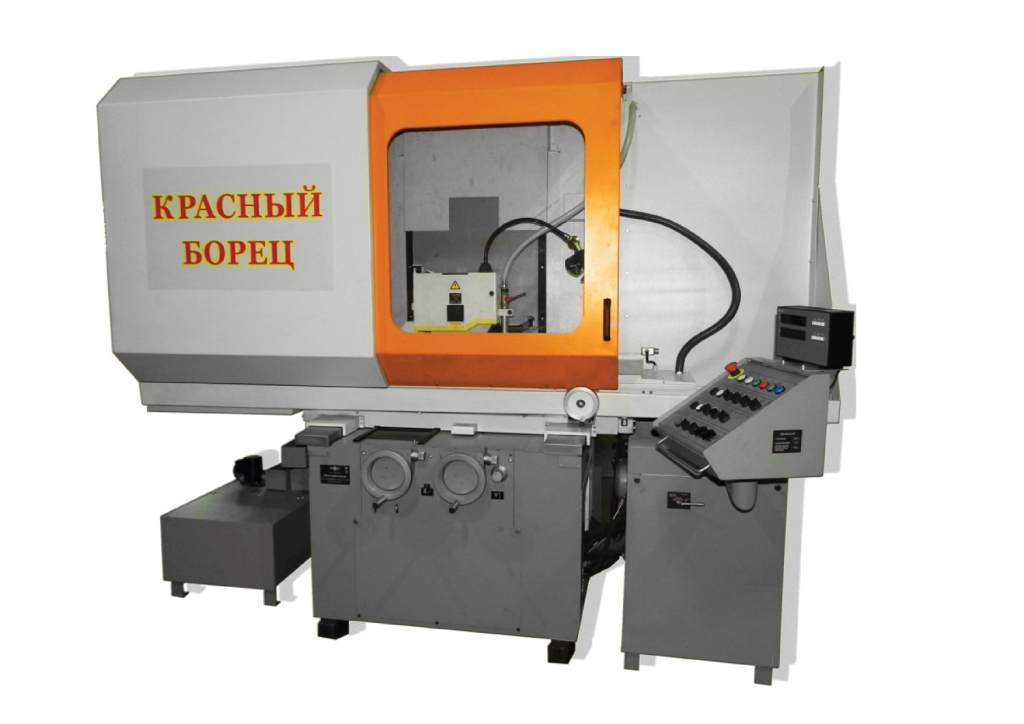
- protection of working zone of machining of cabinet , semi-cabinet type. Cabinet type protection is from stainless steel. Semi-cabinet protection: arrester of closed type with movable opening door with plexiglass is installed on working surface of table, the right part is open.
Add your review