- Index
- Catalog
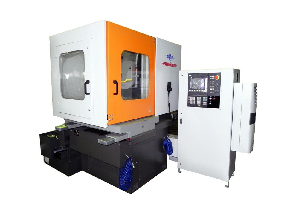
- SURFACE GRINDING MACHINE WITH ROUND TABLE AND HORIZONTAL SPINDLE
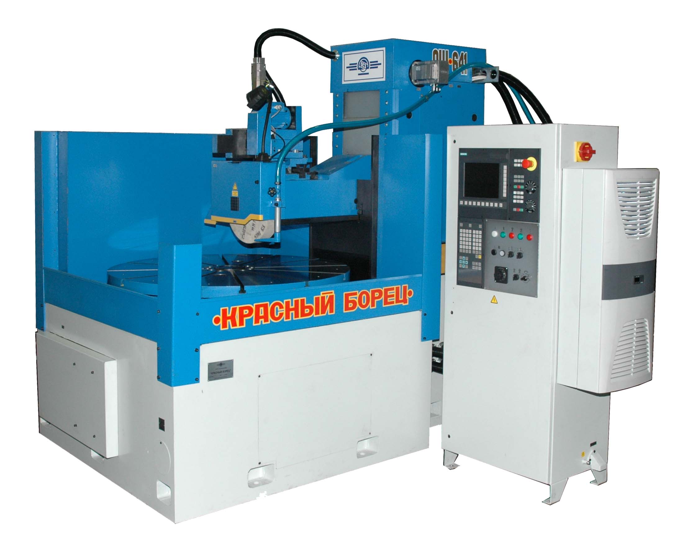
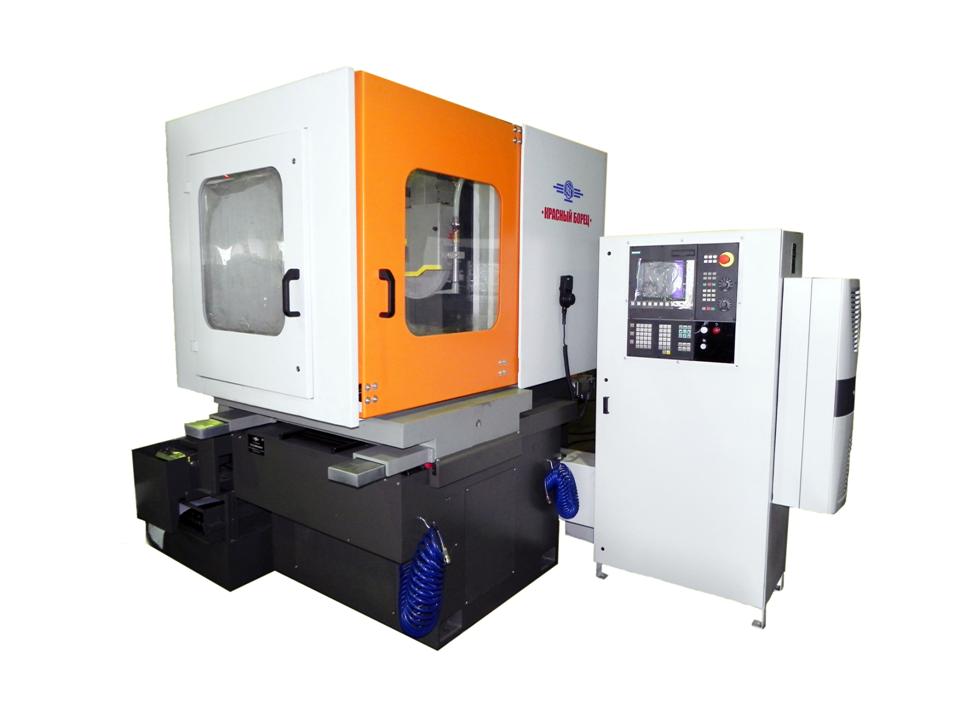
- SURFACE GRINDING MACHINE WITH ROUND TABLE AND HORIZONTAL SPINDLE OSH-641 WITH CNC
SURFACE GRINDING MACHINE WITH ROUND TABLE AND HORIZONTAL SPINDLE OSH-641 WITH CNC
DESCRIPTION
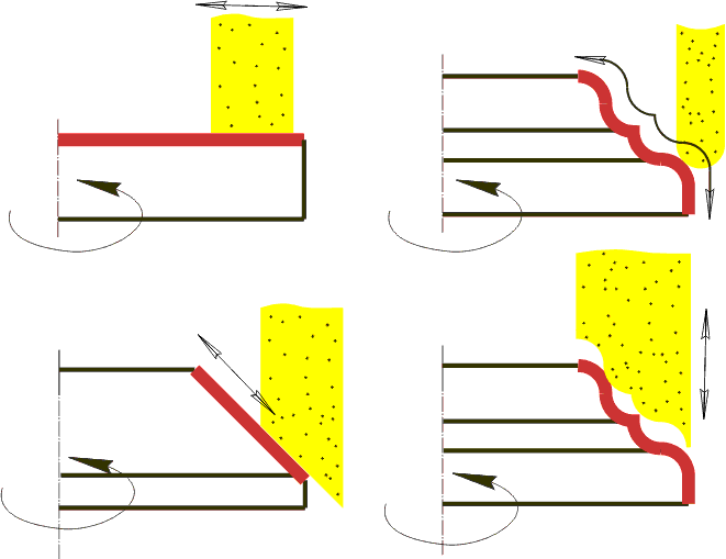
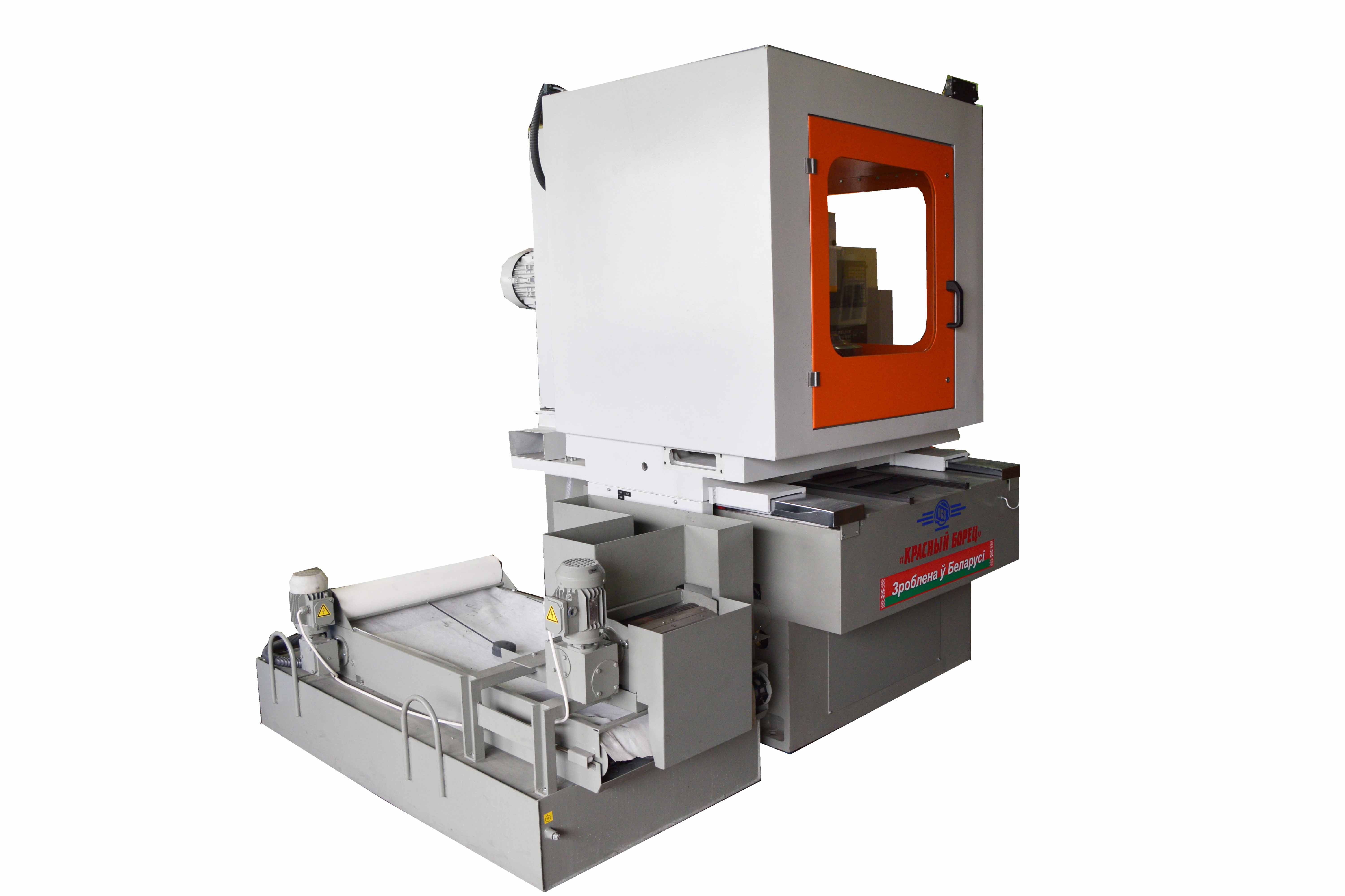
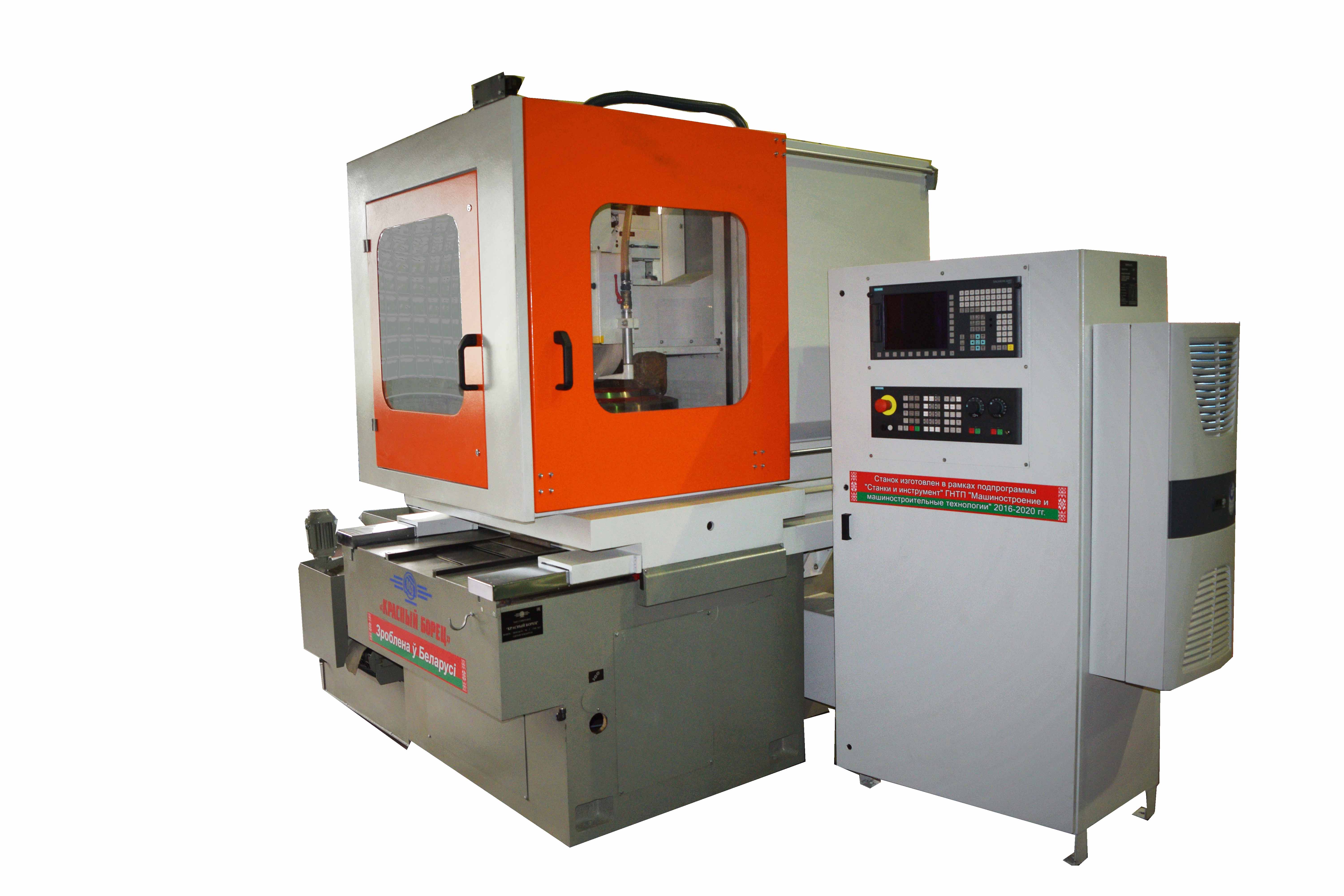
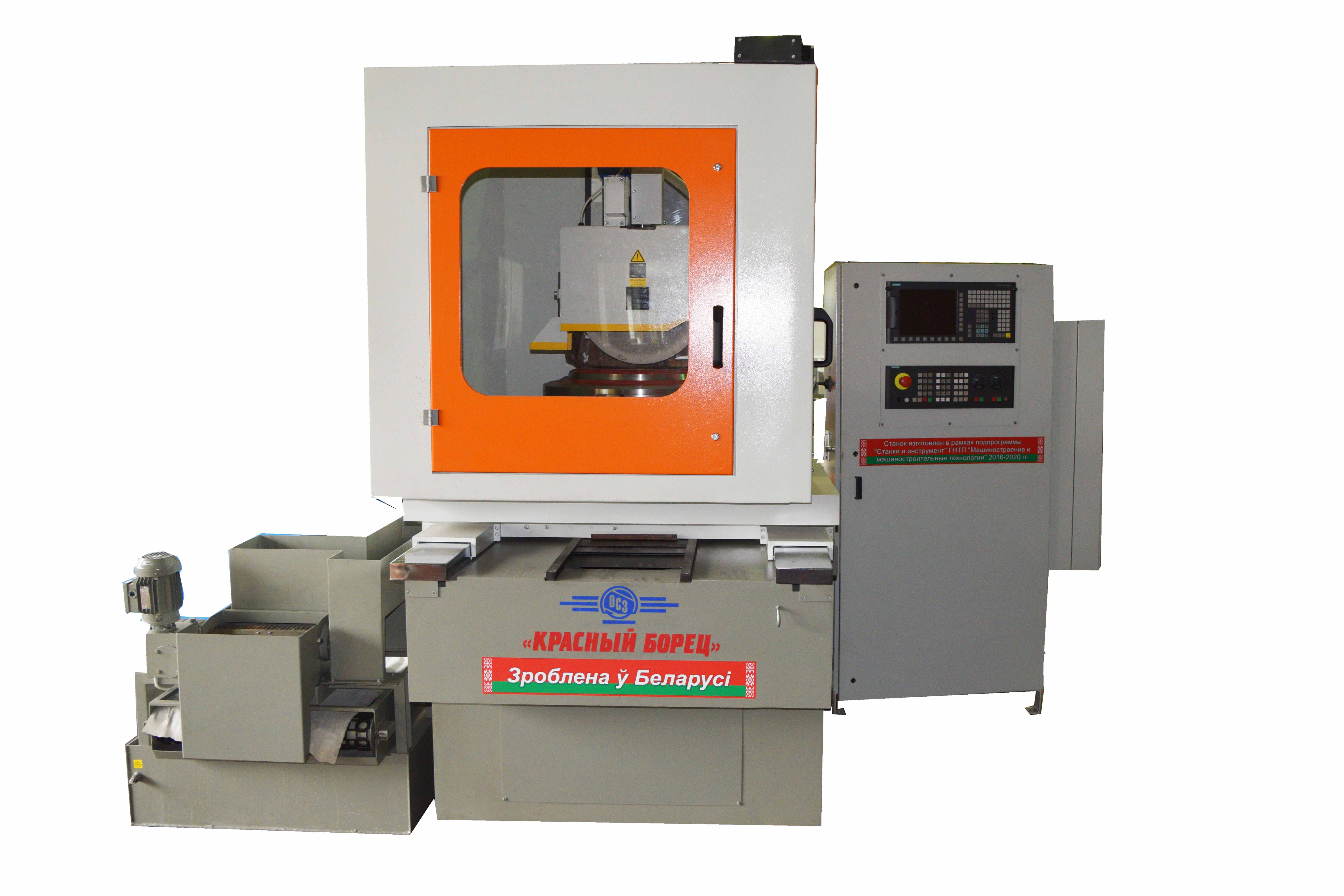
Machine is designed for abrasive processing (grinding) of flat surfaces of parts as well as profiles being combinations of straight line sections, circle arcs and other precisely set curves in rectangular system of coordinates fastened on the electromagnetic chuck of rotary table or on the rotary table face plate.
Field of machine use is enterprises of serial and small branch production.
Machine is manufactured as per technical requirements – TY RB 300053207.321-2007.
Kinematic diagram of machine must provide the following motions:
- rotation motion of rotary table;
- wheel head vertical travel (coordinate Y);
- column cross travel (coordinate Z)
- grinding wheel rotation;
- dressing mechanism diamond roller rotation;
- dressing mechanism diamond roller travel from initial position into working one and back.
DESIGN ADVANTAGES
- CNC system – SINUMERIK-828 D with drive SINAMATIC or NC system- SIMATIK S7-1200
- Wheel head bearings – FAG, IBC
- Use of high precision play-free rolling ball-screw pairs in units of feeds provides smooth high precision play-free positioning
- Circular travels converters – SKB IS, FAGOR
- Linear guide ways – SCHNEEBERGER
- All working travels of machines are automated. There is an electronic hand wheel for travel over coordinates Y and Z with discreteness 1 mkm
- Technical specifications
- Design description
- Delivery set
- Options
- Video
- Reference-list
- Reviews
-
Diameter of working surface of round table
1200 mm
-
Maximum diameter of machined items
1200 mm
-
Maximum height (when the wheel is new together with electromagnetic chuck)
450 mm
-
Max external diameter of worn wheel
210 mm
-
Internal diameter of grinding wheel
127 mm
-
Maximum column travel
610 mm
-
Flatness
10 mkm
-
Parallelism
16 mkm
-
Roughness of surface machined by wheel periphery, Ra
0,63 Ra
-
Maximum mass of installed work piece (together with attachment and electromagnetic chuck)
2000 kg
-
Maximum distance between table mirror and spindle axis
650 mm
-
Grinding wheel diameter
400 mm
-
Grinding wheel height
20...100 mm
-
Grinding wheel bore diameter
127 mm
-
Main drive power
11 kw
-
Grinding spindle rotation frequency
1450 mm/min
-
Coolant-lubricant feed pump productivity
100 L/min
-
Coolant treatment
MAGNETIC SEPARATOR
-
Coolant-lubricant tank capacity
250 L
-
Angle of table turning incline
- DEGREES
-
Discreteness of vertical travels (of wheel head)
1 mkm
-
Discreteness of cross travels (of column)
1 mkm
-
Discreteness of vertical travels (of dressing mechanism plunger)
5 mkm
-
Limits of table face plate travels speeds (coordinate C)
2...30 mm/min
-
Limits of cross column travels speeds (coordinate Z)
10...630 mm/min
-
Limits of vertical wheel head travels speeds (coordinate Y)
0,001...0,3 mm/min
-
Limits of cross dressing mechanism carriage travels speeds
10...800 mm/min
-
Overall dimensions (length x width x height)
3750 x 3500 x 2250 mm
-
Mass
9000 kg
Machine arrangement
Column travels over guide ways of the base on Т-shaped bed consisting of two cast rigidly joined between each other parts – bed and base. Round table and table drive mechanism with reduction gear are located on the top plane of bed in its borings. Wheel head travels over vertical guide ways of column, travel is realized from reduction gear fastened on the column top supporting plane.
Grinding wheel dressing is realized by rotating diamond roller of rotary dressing mechanism which is fastened on horizontal pad in the left corner in niche of the rear part of the bed.
From behind to the left of the bed the tank of coolant-lubricant feed system is installed, to the right from it there is a hydraulic station and to the right of hydraulic station there is an electric cabinet. Control desk is located to the right in front of the machine and is fastened with possibility of its turning.
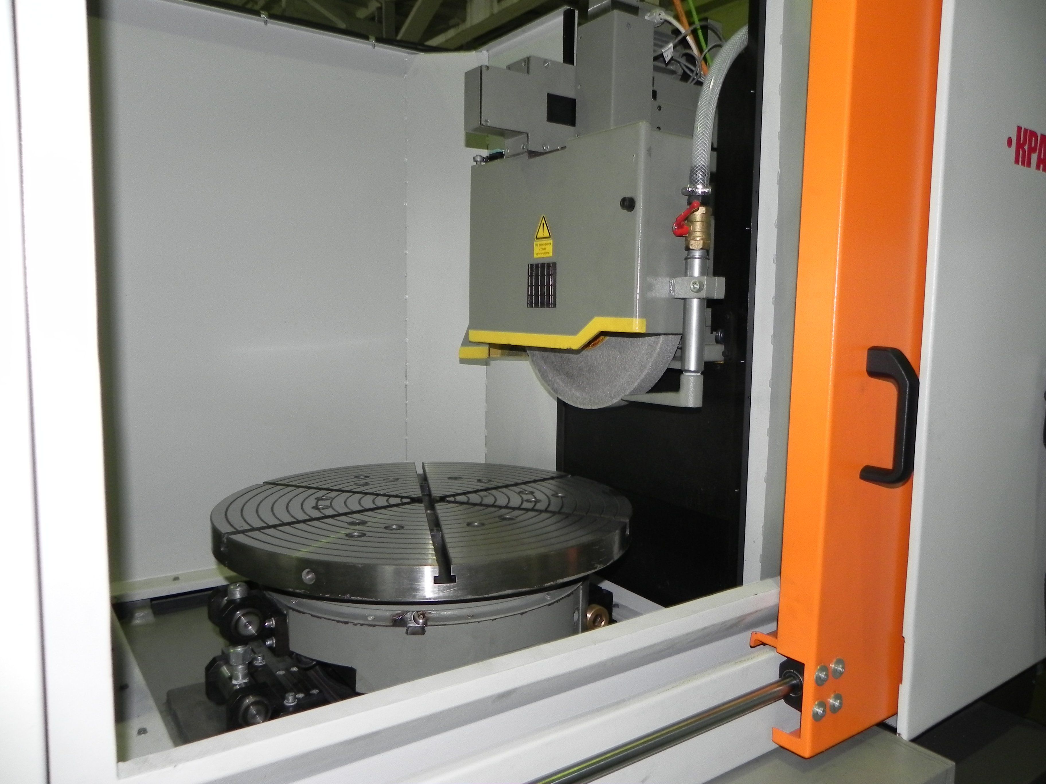
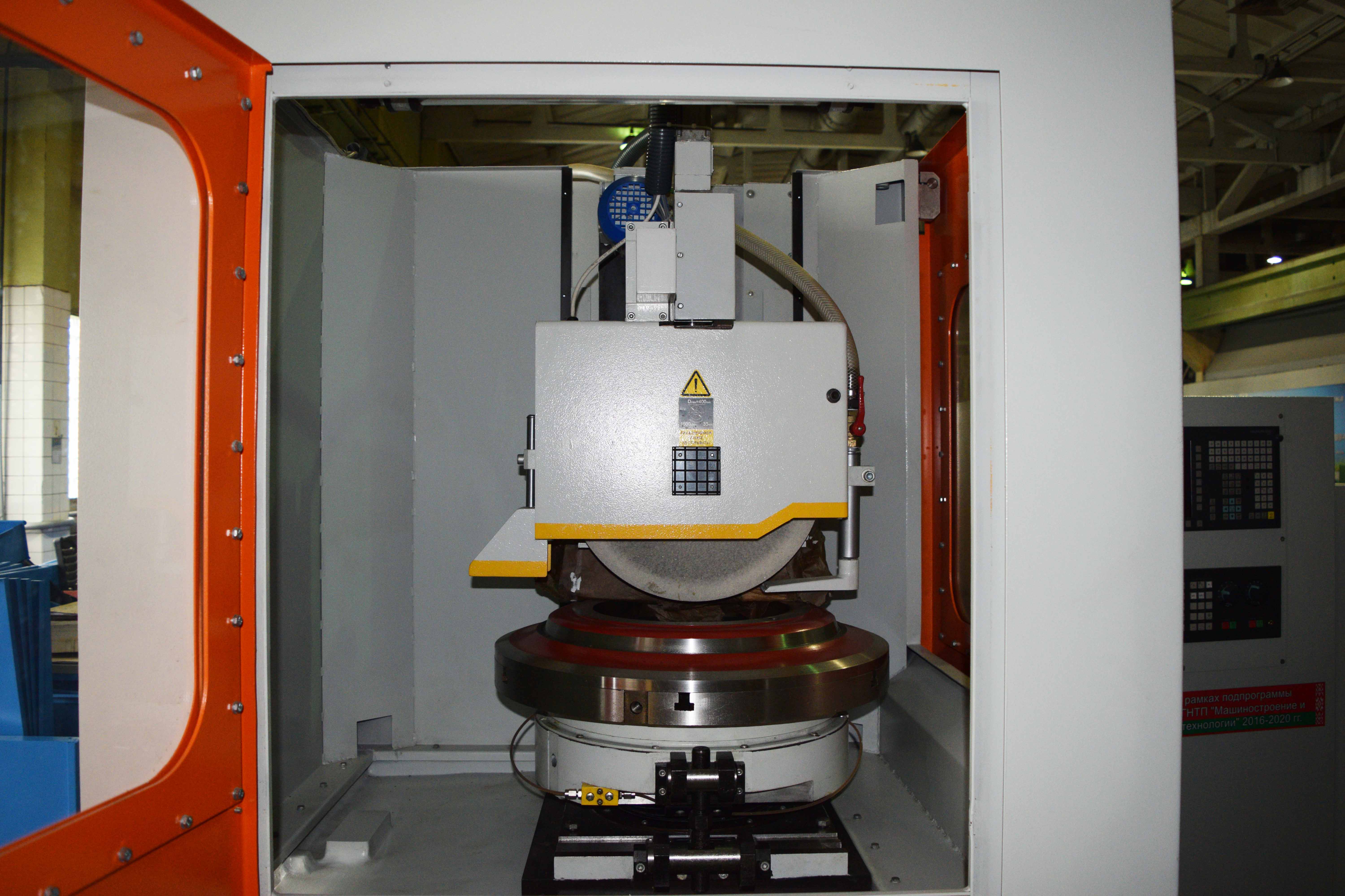
Round table
Table face plate with diameter 1200 mm bases by lower supporting circular plane when rotating on circular guide way of table body, so, in such a way the end circular plain slideway is created. Lubricating material is supplied under adjustable pressure for decreasing the sliding friction and providing uniformity of rotation of face plate between rubbing surfaces (mode of “boundary friction” is achieved).
Face plate is connected with spindle by flat elastic disc which is fastened on spindle and centres face plate relative to spindle. Face plate receives drive from servo drive through gear belt drive and reduction gear of the firm “Wittenstein alpha”.
Electromagnetic chuck is installed on the top end surface of face plate for fastening the machined parts. Collector of voltage supply to electromagnetic chuck is fastened at the bottom on spindle.
Wheel head.
Wheel head spindle rotation axis has a horizontal arrangement (parallel to table face plate face).
Wheel head body on closed linear slide roller bearing units travels over vertical guide ways (file-hard bars, V- shaped and flat ones) of column. Head travel drive is from programmable drive of the firm Siemens providing vertical feed of head with discreteness 1 mkm through reduction gear installed on top the column.
Vertical feed of grinding wheel on cutting-in can be realized in automatic mode (with setting the parameters of mode from machine control desk) as well as in manual mode by means of electronic hand wheel.
Spindle bases on precision radial - thrust bearings.
Spindle rotation is realized from electric motor through torsion coupling.
Column.
Column travels in cross direction on closed roller linear guide ways fastened on the base.
Column travel drive is from programmable drive of the firm Siemens through belt transmission onto rolling screw-nut.
Column cross travel can be realized in automatic mode with setting the parameters of mode from machine control desk or manually by means of electronic hand wheel.
Vertical feed mechanism.
Vertical feed mechanism realizes vertical travel of wheel head and is fastened on upper surface of column.
Mechanism consists of electric motor installed on body and coupling connecting electric motor with reduction gear.
Grinding wheel housing.
Grinding wheel housing is executed welded from sheet metal according to the requirements of safety measures norms as per GOST 12.3.028.
Micro switch blocking grinding wheel rotation when the cover is open is installed under front housing cover.
Grinding wheel flanges.
Grinding wheel is installed between flange and face plate through gaskets which are tightened by screws.
Grinding wheel balancing is realized by travel of balance weights in the slot of the first flange.
Removal of grinding wheel from spindle taper is produced by the screw М24 which rests into the face plate nut by its face when unscrewing it and removes grinding wheel together with flanges.
Dressing mechanism
Dressing mechanism is arranged on the pad from behind -to the left from bed.
Grinding wheel dressing is realized during setting the bracket with block of dressing by hydraulic cylinder into working position at which dressing block spindle axis is parallel to grinding spindle axis. Grinding wheel travels relative to rotating but coordinate immovable diamond roller. As grinding wheel can travel simultaneously over two coordinates (Y and Z), then it can be dressed over periphery as well as over face.
Control system
- Control system – Sinumeric 828D of the firm “Siemens’;
- Feeds electric drives – servo drives Sinamics of the firm “Siemens”;
- Low voltage equipment of the firm “Siemens”;
- Limit switches of the firm “Balluff”;
- Feedback of travels over axes Y, Z control is realized by photo pulse converters of the firm “Fagor”.
The delivery set of the machine consists of:
- machine assembled;
- system of coolant feed and treatment;
- hydraulic station;
- electric cabinet;
- control desk with CNC system;
- set of spare parts, quick wearing parts and tools;
- shoe for machine installation - 1 set (15 pcs.);
- grinding wheel flanges– 2 sets (1 set is installed on the machine);
- arbour for grinding wheel static balancing - 1 pc.;
- wrenches GOST 11737:
- 7812-0382 S=19 - 1 pc.
- 7812-0384 S=24 - 1 pc.
- face contactless switch - 1 pc.
- filter element - 1 pc.
- belt on table drive - 1 pc.
- set of in-line documentation.
Dressing mechanism on wheel head
Cabinet protection
Rotary dressing mechanism on bed
Magnetic and electromagnetic chuck


