- Index
- Catalog
- SURFACE-PROFILE GRINDING MACHINES
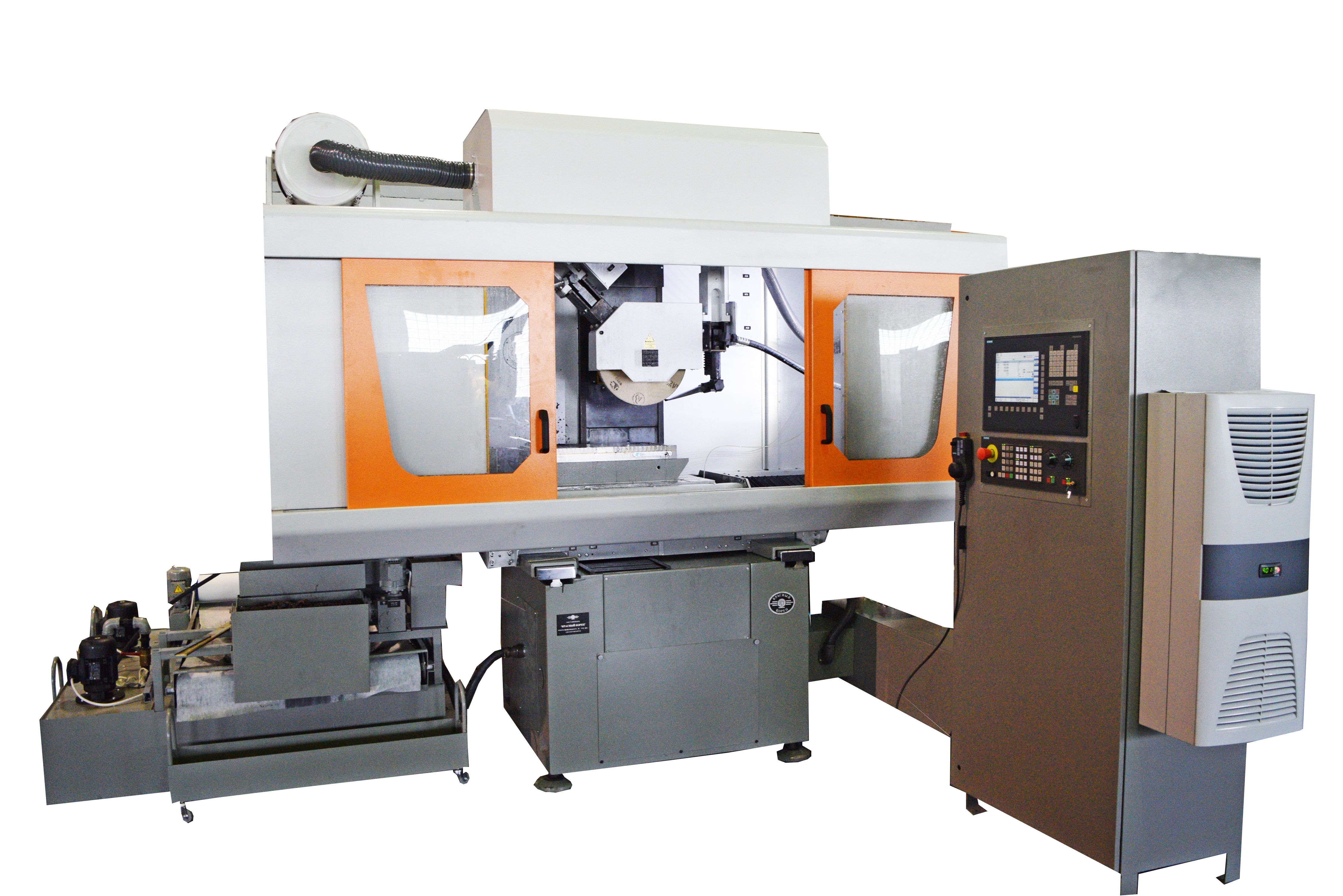
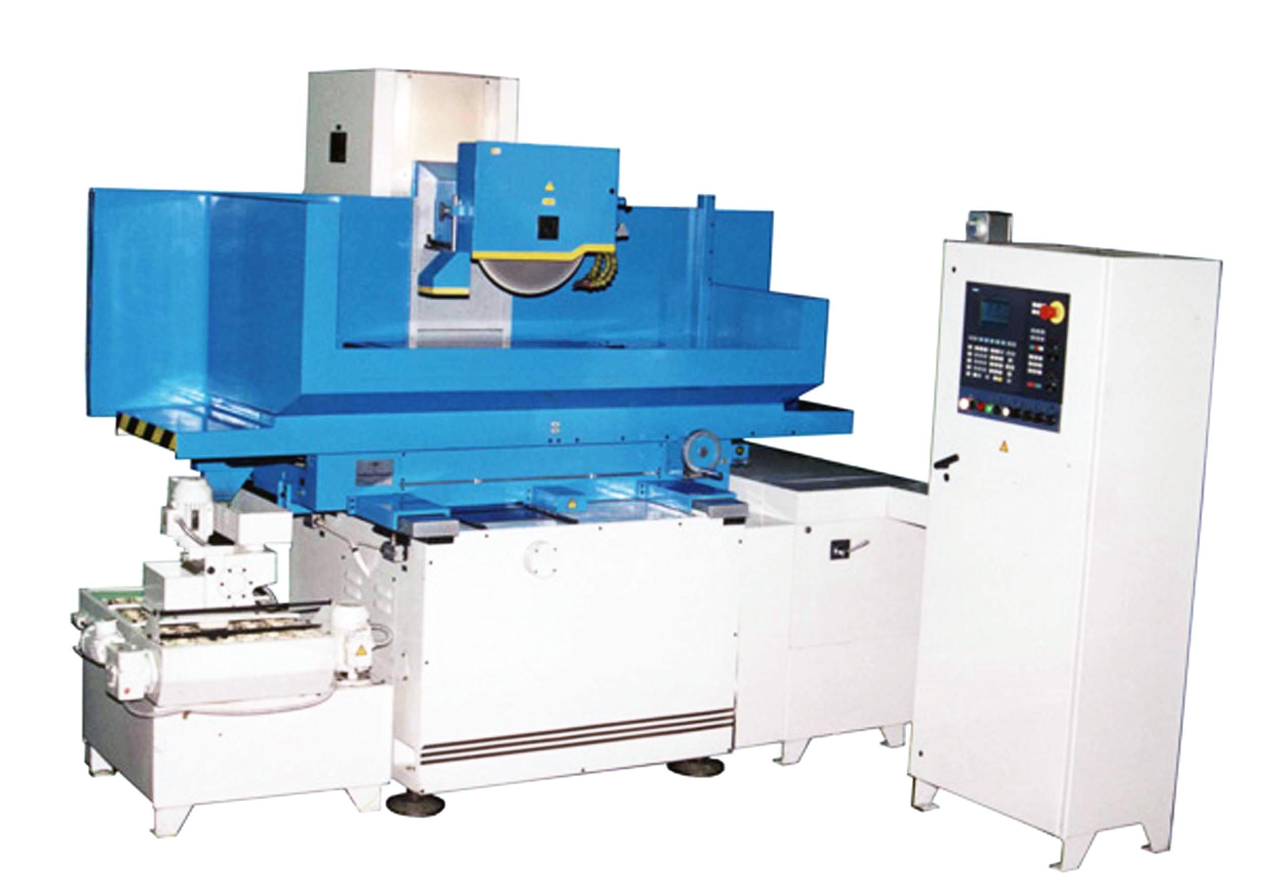
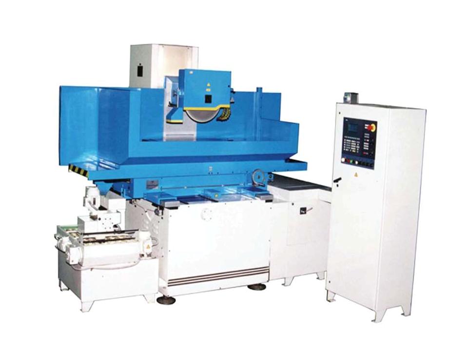
- SURFACE & PROFILE GRINDING SEMIAUTOMATIC MACHINE WITH CNC OSH-620F3
SURFACE & PROFILE GRINDING SEMIAUTOMATIC MACHINE WITH CNC OSH-620F3
DESCRIPTION
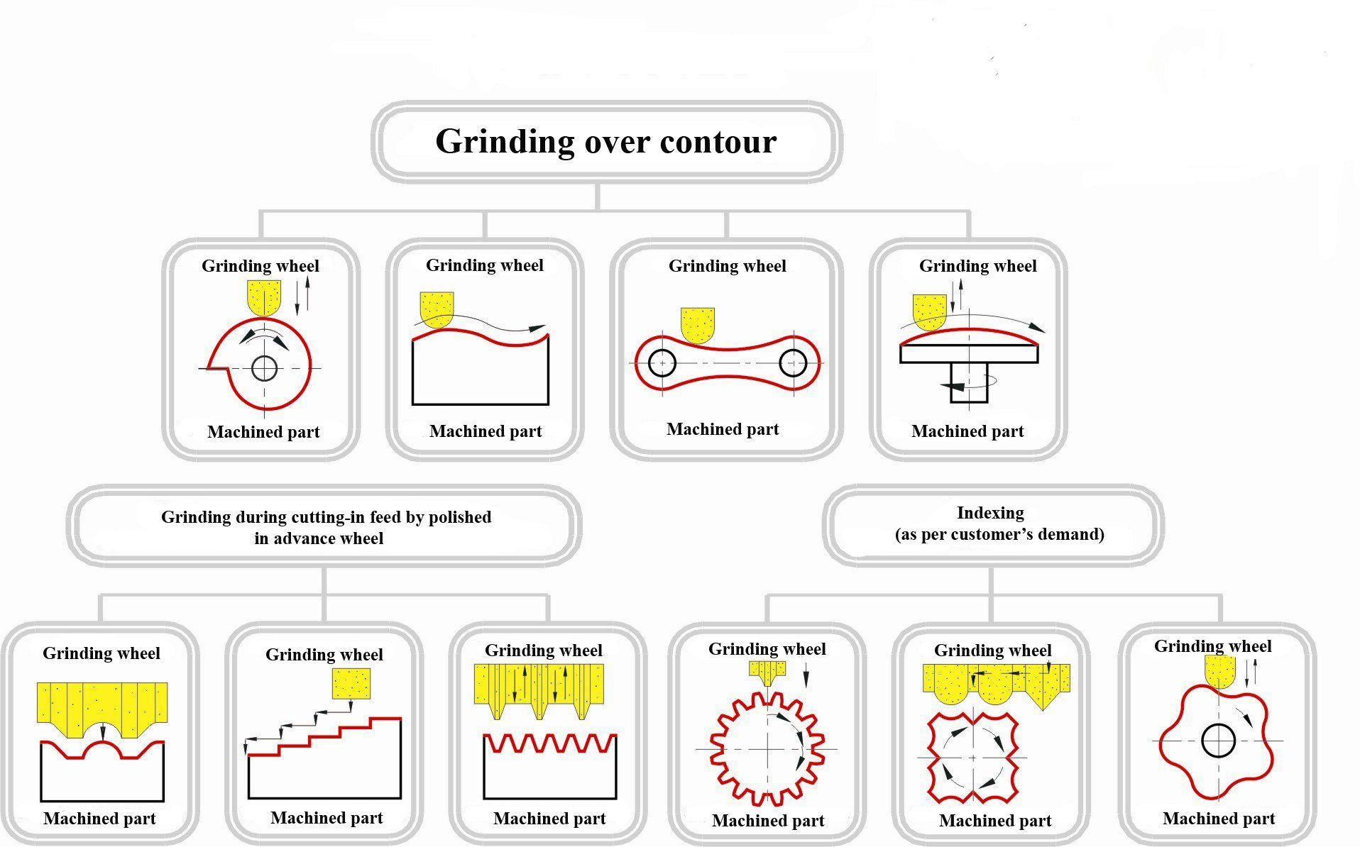
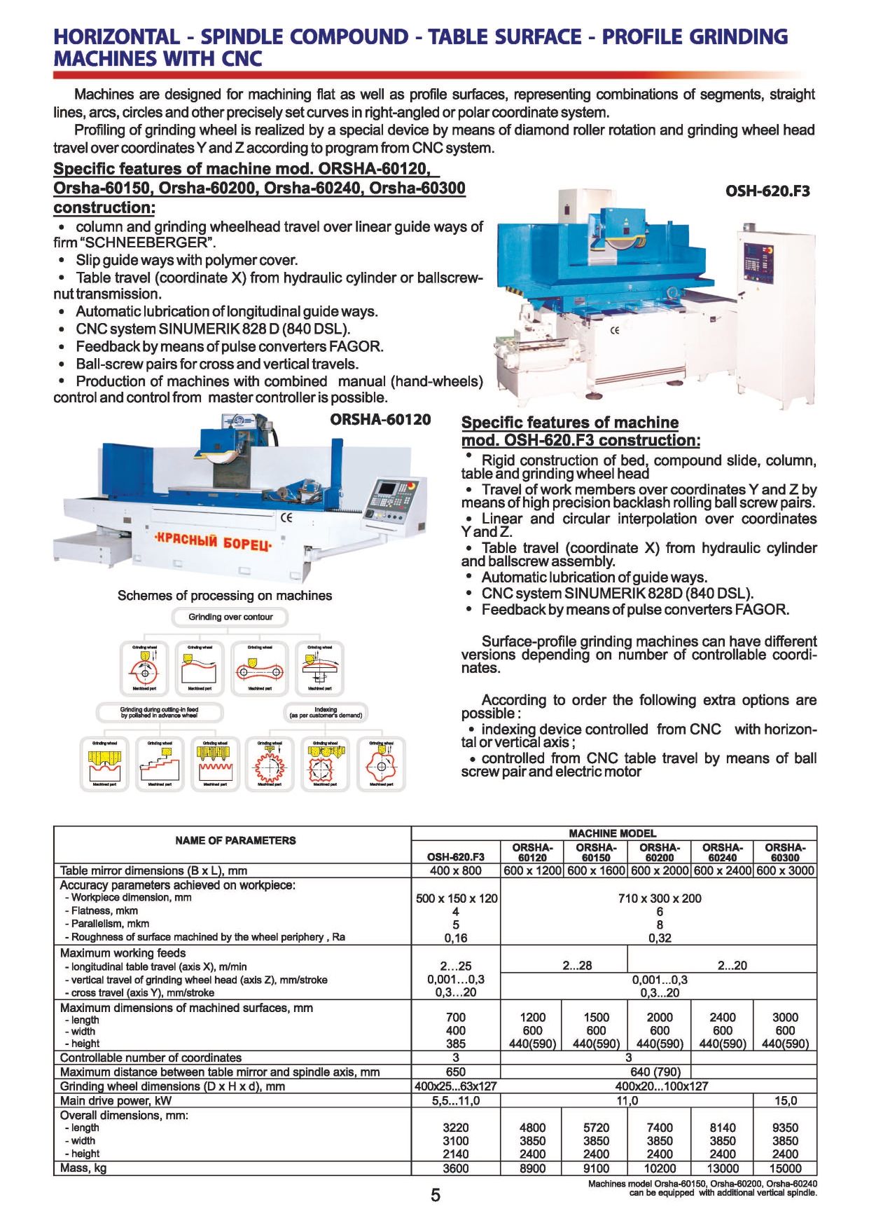
Semiautomatic machine with CNC model OSH-620F3 is designed for grinding of flat surfaces and curvilinear profiles corresponding combination of sections, straight lines, arcs, circles and other intelligent curves in rectangular and polar coordinate system of coordinate by pendulum grinding by method of copying or execution of the contour.
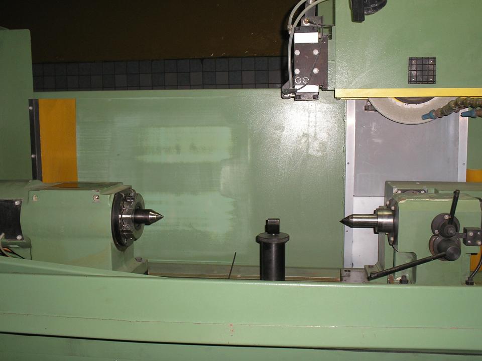
When equipping the machine with indexing head and tailstock machining of slot and tongue-and-groove surfaces of the parts type of bodies of revolution is possible when basing the part in centres or in a chuck.
Field of machine use is enterprises of small-scale and serial production.
Grinding wheel profiling is produced by dressing mechanism rotating radius diamond roller installed on machine table.
Machine can be equipped with CNC system of the firm “Siemens”, “Mitsubishi” and “Fanuc” and incremental sensors (converters of linear travel) over two programmable coordinates (cross travel of compound slide - coordinate Z, vertical travel of wheel head – coordinate Y).
Kinematic diagram of machine provides the following motions:
- grinding wheel rotation;
- vertical travel of wheel head;
- cross travel of table;
- longitudinal travel of table;
- rotation of contour dressing mechanism diamond roller;
- turn of headstock spindle.
DESIGN ADVANTAGES
- Driven elements traveling is realized over steel hardened guide ways on rolling contact bearings by ball-screw pairs
- Wheel head spindle rotation is realized by induction electric motor with revolutions variable frequency
- Use of high precise angular ball bearings of the firm IBC for grinding spindle (in front support - 4 pcs., in rear support - 2 pcs.)
- Grinding wheel working surface profiling is executed by dressing mechanism diamond rollers with radius at the top R=0,7 mm and R=2,5 mm in automatic mode according to program
- Automatic lubrication of guide ways
- Machine control is realized by CNC system from the electric cabinet control panel located in front of working zone according to control program (CP)
- Use of proximity sensors of the firm “Balluff”, cooler of electric cabinet of the firm RIТTAL
- Cooling system tank with pump with productivity 50 l/min and magnetic separator
- Technical specifications
- Design description
- Delivery set
- Options
- Video
- Reference-list
- Reviews
-
Machine accuracy class
High
-
Table mirror width
400 mm
-
Table mirror length
800 mm
-
Dimension of item sample
500 x 150 x 120 mm
-
Flatness
4 mkm
-
Parallelism
5 mkm
-
Roughness of surface machined by wheel periphery, Ra
0,16 Ra
-
Compound slide maximum travels
400 mm
-
Table maximum travels
700 mm
-
Maximum distance between table mirror and spindle axis
650 mm
-
Grinding wheel diameter
400 mm
-
Grinding wheel height
25...63 mm
-
Grinding wheel bore diameter
127 mm
-
Main drive power
5,5...11,0 kW
-
Grinding spindle rotation frequency
1750...2300 rpm
-
Maximum length of machined surface
700 mm
-
Maximum width of machined surface with grinding wheel run-out (at wheel height 40 mm)
445 mm
-
Maximum height of machined surface
385 mm
-
Limits of table longitudinal travel (axis X)
2...25mm/min
-
Wheal head vertical travel limits (axis Z)
0,001...0,3 mm/stroke
-
Cross travel limits (axis Y)
0,3...20 mm/stroke
-
Controllable number of coordinates
3
-
Maximum length of machined part in heads
400 mm
-
Maximum diameter of machined parts in heads
300 mm
-
Centres height
180 mm
-
Speed of table travel
2...25 m/min
-
Speed of wheel head adjustment travels
0,6 m/min
-
Speed of compound slide adjustment travels
4 m/min
-
External diameter of installed diamond roller
125 mm
-
Internal diameter of installed diamond roller
32 mm
-
Radius at the top of installed diamond roller
0,7 mm
-
Discreteness of wheel head, table and compound slide travel
0,001 mm
-
Discreteness of headstock travel
0,001 degree
-
Overall dimensions (length x width x height)
3220 x 3100 x 2140 mm
-
Mass
3600 kg
Machine arrangement.
The machine base is the bed on which compound slide, column, cross feed mechanism are installed.
Machine compound slide provides longitudinal and cross travel of table on which electromagnetic chuck and contour dressing by rotating diamond roller mechanism are installed.
All driven elements traveling is realized over steel hardened guide ways on rolling contact bearings.
Vertical travel of wheel head is realized over column guide ways by vertical feed mechanism through reducer.
Table which travels by means of hydraulic cylinder is installed onto longitudinal guide ways of compound slide. Vertical travel of wheel head, cross travel of table is realized by ball-screw pairs. Hydraulic equipment is fulfilled as a separate unit and installed to the right of the machine and cooling system is to the left. Electric automation cabinet with CNC system is located from the right side from the front.
CNC system provides:
- simultaneous control over coordinates Y, Z axes;
- axes independent functioning;
- linear and circular interpolation over programmable axes;
- support of grinding wheel constant linear set speed of cutting in case of its tear and wear.
Description of machine units.
Bed.
Machine bed is an iron casting of box form and is a foundation for machine units installation. On its top pads rolling guide ways for compound slide travel are fastened and column is installed. Right guide way is flat, it perceives vertical loads and left U-form guide way perceives vertical as well as horizontal loads.
Cross feed mechanism is installed on the front wall of bed, to the left on side surface there is a cross stroke limitation mechanism. Protection of cross guide ways is realized by shields.
Column.
Column provides vertical travel of wheel head over closed rolling guide ways.
Guide ways of surface are formed by column itself and bars screwed to its front surface. Front and rear window of column are protected by set of shields traveling in slots of side bars.
Micro switch is installed in top part of column for limitation of wheel head travel. Vertical feed mechanism is installed on lower surface of column.
Left cross guide way.
Left cross guide way is of U-form in section and perceives vertical and horizontal loads. Guide way with rollers is assembled with preload. Side tension of rollers is created by wedge with its following fixation.
Compound slide
Compound slide provides cross travel of table. Upper guide ways (V-shaped and flat ones) serve for longitudinal travel, and lower U-shaped and flat ones are for cross travel. Bracket of cross feed mechanism nut is fastened to the lower pad of compound slide. Hydraulic cylinder is installed between upper guide ways. Converter of linear travel is fastened on brackets on front and rear walls of compound slide.
Table
Table has a working surface with three T-shaped slots on which attachment (or electromagnetic chuck) and dressing mechanism is installed. At the bottom there are V-shaped and flat rolling guide ways for longitudinal travels. Wings for compound slide guide ways protection are fastened to side walls of table. Collecting coolant –lubricant from table takes place in lower place and discharge - through aperture in rear wall of table into collector and then to cooling tank.
Cross feed mechanism
Cross feed mechanism realizes cross travel of compound slide and is fastened on the front wall of bed. Torque from electric motor is transmitted through coupling to screw - rolling nut gear which is connected with compound slide by means of bracket.
Enclosure
Enclosure of machine is a welded frame installed on the table and designed for protection against coolant-lubricant splashing during work. Enclosure of two types can be installed:
- lower tray with frame and set of prefabricated shields;
- skeleton sheeting with closed top and movable sliding door of cabinet type.
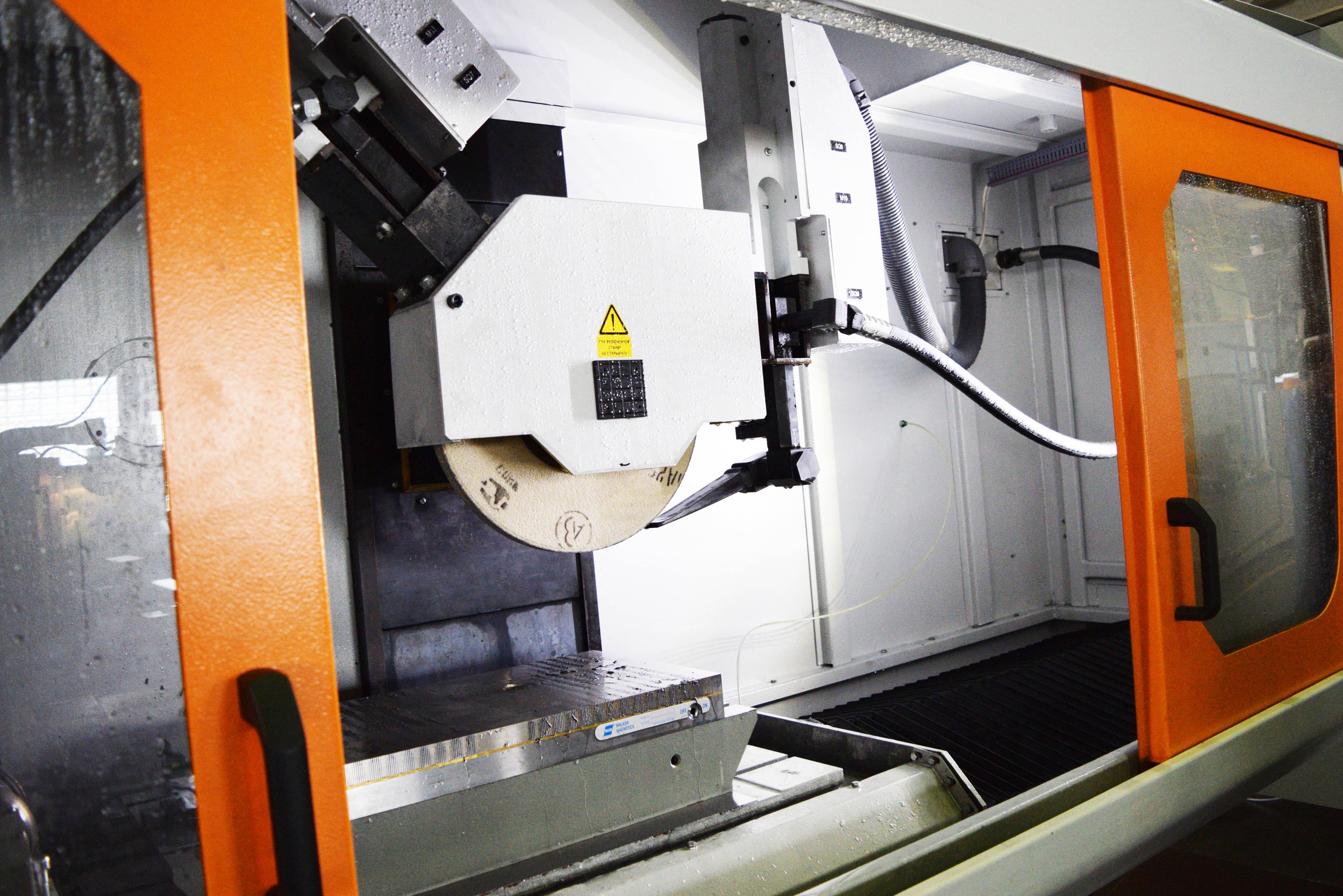
Wheel head
Wheel head consists of cast-iron molded case with vertical guide ways and spindle installed in bushing. For providing the gapless connection, the bushing is covered with epoxide compound in body along the diameter. Spindle is installed on high precision thrust rolling bearings assembled with preload. Rotation from electric motor through half-couplings and drive shaft is transmitted onto wheel head spindle. Bar with fastened on it linear travels converter is installed in the rear part of body.
Dressing mechanism
Grinding wheel dressing over profile is fulfilled on the machine by means of dressing mechanism. Mechanism is installed to the right on the machine table and consists of body (or two bodies) in which spindle is mounted on high precision bearings. Diamond roller is installed on spindle face, roller rotation drive is from electric motor through belt transmission. Caves of bearings are protected from coolant-lubricant and abrasive ingress by a cup.
Grinding wheel flanges Grinding wheel is installed between flange faceplate through gaskets which are tied by screws.
Grinding wheel balancing is realized by moving balance weights in the slot of the front flange. Grinding wheel flanges are installed on wheel head spindle cone and tied by screw.
Delivery set of machine includes:
- machine assembled;
- coolant feed and treatment system;
- hydraulic station of table drive and lubrication;
- electric automation cabinet with CNC system;
- contour dressing mechanism;
- electromagnetic chuck 630 x 400 mm;
- set of spare parts, tools and accessories;
- set of operational- technical documentation;
- control program (CP) of part machining;
- grinding wheels 400 x 127 x 50 – 2 pcs.
Gun for blow-off by air. This option includes a special gun with polyvinyl tube through which air is supplied from extranet under pressure. Air supply is realized onto block installed on the machine bed and further into the gun which is located on the front surface of bed in the zone of the operator’s location. The operator can produce the blow-off removed from the table or electromagnetic chuck machined parts with compressed air by pressing the gun lever.
System of coolant feed and treatment with magnetic separator and filter –conveyor. This option includes tank with pump for coolant-lubricant feed into the zone of machining and filter –conveyor with roller filtering cloth and also magnetic separator which is installed on the frame of filter-conveyor. Filtration of coolant-lubricant takes place at first through magnetic separator, then through filter-conveyor. Capacity of magnetic separator is 50 l/min, of filter-conveyor is 100 l/min.
Ball screw transmission (rolling screw-nut) onto table longitudinal travel. This option includes rolling screw-nut transmission, installed between top guide ways of bed. Transmission serves for table travel. Rotation of feed screw is realized by pulleys of belt gear transmission from electric motor Siemens installed on plate from the right side of the bed. Limitation of table travel is realized by compound slide micro switches.
Equipping with rotary table with controllable coordinate. Demountable rotary table with electromechanical servo drive with vertical axis of rotation. Turn of table faceplate (coordinate B) is controlled by CNC system.
Equipping of machine with high-speed electric spindle or spindle Fortuna. Machine is equipped with wheel head with horizontal spindle. Electric spindle with heightened number of revolutions (n=42000 rpm) or spindle Fortuna can be used as a spindle.
Equipping of machine with rotary index head with controllable coordinate (C) and tailstock (indexing attachment).
Indexing attachment consists of headstock and tailstock installed on general plate. Headstock consists of body in which spindle is installed on high precision bearings. A cup is fastened to body on which reducer is installed. Rotation from electric motor is transmitted to spindle through reducer and coupling. Accuracy of turn is controlled by incremental rotary sensor. Tailstock consists of body inside of which poppet sleeve travels. Withdrawal of poppet sleeve is realized by trigger installed on the axis. Supply of poppet sleeve is realized by a spring. Poppet sleeve is clamped by screw through bushings.Equipping the wheel head with grinding wheel dynamic balancing device. This option includes balancing head of flange type with contactless transmitter, vibration sensor and electronic device. Use of this device allows to produce automatic balancing of rotating grinding wheel on machine with minimum imbalance.
Equipping with device of part position control. This option includes mechanism consisting of bracket on which axis with lever is fastened. Touch sensor with probe is fastened in the lever. Lever turns on the axis by linear pneumatic cylinder. Touching the machined part is produced by means of touch sensor of the firm “Renishaw” and its linear coordinates are determined which afterwards are used in the control program (CP) of machining.
SURFACE & PROFILE GRINDING SEMIAUTOMATIC MACHINE WITH CNC OSH-620F3